seikeinlemming
Petty Officer 2nd Class" & 2020 Splash of the Year
- Joined
- May 23, 2011
- Messages
- 140
No Title
All images at the bottom, something wasn't letting me post that many in line and have them show up, so I reference the photo with each paragraph.
Rounding out the home stretch of getting the engine running on air. We are still shooting for next weekend, if we miss it, it won't be by much. This was kind of a unique piece to machine, so I'm specifically showing it.
The particular piece mounts in the linkage that moves the sliders back and forth that direct steam into each cylinder, so there will be two that are identical to each other (one for each cylinder). Due to how this runs, it needed to be machined with a curve to the entire piece.
[Image 5]To accomplish this, we have a rotary table that mounts on the milling machine. This allows me to spin a piece 360 degrees and make cuts into it at different angles. We put a piece of sacrificial steel that mounts to the table and extends out to where we need to mount the piece to be machined. In the photo below you can see the sacrificial steel mounted to the table with the exact center towards the camera indicated by a sharpie plus sign with a tiny indentation into the steel. The actual piece we are making is then mounted to the far side (roughly 16" from 0,0).
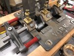
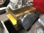
[Image 1] Here is a closeup of the piece being machined. This started off as an 8x4 block of steel (outlined in sharpie on the base). By turning the rotary table on the far side, I am able to make all of the cuts that are on a curve as well as doing the straight edges. Here is where right triangles and corresponding angles come in very close, and half a degree moves the piece an entire tenth of an inch - once again, precision is a must.
[Image 2] Here is the plan for this particular piece. You can see what dimensions are given, and everything else (angles etc) must be calculated from this. You can also see the slight curvature of the piece.
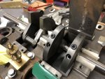
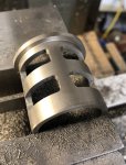
Another angle of the link in the milling machine. Showing a "straight" cut which is really cut at a slight angle to the piece (think like spokes on a bicycle wheel and their relation to the wheel/tire).
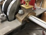
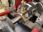
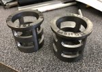
The link after it is taken out of the mill.
Attachments
Last edited:


