Steam Launch parts acquired

seikeinlemming

Petty Officer 2nd Class" & 2020 Splash of the Year
Joined
May 23, 2011
Messages
140
No Title

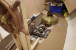
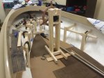
The elves have been busy working through the night (2 am? And no fingers are on the workshop floor!). Last night I started building out the aft bench seat and steering wheel pedestal to decide height/location of these items. Obviously this will all be rebuilt, but before we go slicing up mahogony to figure out something doesn't work, it seemed best to frame it out of cheap studs and flakeboard from Lowe's. When the template is complete we will be able to walk/sit on everything.

In the second photo you can see the positioning of the wheel, steam engine, and boiler (round brass cap sitting on far side of the engine base). Right now everything is in the designer-suggested location for these items, but we will move them slightly as necessary.

Past the boiler you will see a blue cooler. This will be the location of an additional U-shaped bench, yet to be designed.
 

Attachments

  • photo243285.jpg
    photo243285.jpg
    164 KB · Views: 5
  • photo243286.jpg
    photo243286.jpg
    149.6 KB · Views: 5
Last edited:
pckeen

Commander
Joined
Jun 20, 2012
Messages
2,067
So does the wheel turn the tiller via pulleys? Love the wheel by the way.
 

seikeinlemming

Petty Officer 2nd Class" & 2020 Splash of the Year
Joined
May 23, 2011
Messages
140
pckeen -

All turning will be done through a modern-day hydraulic steering system (the parts of which were purchased from iboats). The wheel's hub was turned down so it fits on a standard tapered wheel mount. In the one previous photo, you can see the round black SeaStar unit, the hydraulic lines will merely run down the column and back to the hydraulic cylinder.

While on the outside this boat will look older, the use of a fiberglass hull, hydraulic steering, and depth-finder will allow us to have some modern day conveniences when desired.
 

seikeinlemming

Petty Officer 2nd Class" & 2020 Splash of the Year
Joined
May 23, 2011
Messages
140
No Title

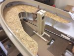
Got a lot done this weekend. The legs are all braced together and the flakeboard bench is in place. Both ends of the bench are cut as curves but not supported. We are not sure how far we want these to go, so as we see how the rest comes together, the ends can be cut shorter to make room for anything else we may want. The vertical spaces from the floor to the seat and the seat backs will be filled in with tongue and groove mahogany which will fill in the gaps that you see now.

Hopefully over the next two weeks I can build the smaller U-shaped bench at the bow and then visually the inside layout will be very close to final.
 

Attachments

  • photo243381.jpg
    photo243381.jpg
    372.1 KB · Views: 3

seikeinlemming

Petty Officer 2nd Class" & 2020 Splash of the Year
Joined
May 23, 2011
Messages
140
pckeen - All support structure and cosmetic finish will be rebuilt/completed in Mahogany.
 
Last edited:
Ned L

Commander
Joined
Sep 17, 2008
Messages
2,266
Very nice. Don't you just love this part of a project,...this is where you need to think about the aesthetics, ergonomics and practicality, and get them to all blend together nicely in the end result.

These launches are fun little boats to put together.
Early in my career when I worked in boatbuilding I built four of these (2 gas, 1 steam, 1 electric)

Out of curiosity, because she is steam and you will need to be tending the firebox and have the valving within easy reach might it be easier to have the wheel on the forward side of the pedistal?
 

seikeinlemming

Petty Officer 2nd Class" & 2020 Splash of the Year
Joined
May 23, 2011
Messages
140
Ned -

The valve gear to switch directions and speed will be located directly in front of the wheel pedestal. As far as keeping steam up, the boiler is based on a design from a friend's boat where you only have to put wood in every 15-20 minutes. It is very efficient (as far as boilers can be efficient), and requires very little attention. People often think that you are continuously shoveling/repositioning fuel in a boiler every few minutes, but we have reason to believe that continuous fuel attention will not be necessary.

Additionally- the firebox door will be facing away from the engine so there is ample room to open the door and feed wood in.
 

seikeinlemming

Petty Officer 2nd Class" & 2020 Splash of the Year
Joined
May 23, 2011
Messages
140
No Title

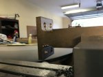
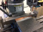
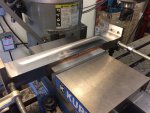
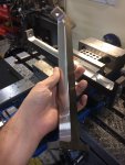
Things are still moving along. We are getting a lot of work done on the steam engine. To give you an idea of how much time gets invested in every single piece (and why the project seems to be taking forever), here are a few pictures of the two connecting rods going from bar of steel to finished piece. Each of these started as 3"x1"x13". They had to be identical, so I machined them both at the same time.

#1 - 1" was taken off both sides in the middle leaving tabs at the ends to fasten to the adjoining parts. After that, a bit that cuts curves is attached and cuts the curved ends. Each cut is done by removing 0.01 of an inch at a time. ( 8 hours )

#2 - While everything is still square, holes are drilled in each end that bolts will go through. The inside of each of these rods was drilled out to make the pieces as light as possible.( 3 hours )

#3 - Because the middle shaft is tapered, I had to put the piece in at an angle to align to the bottom of the curves at the same height. Cutting straight across then made the straight edge that was on a taper. ( 3 hours )

#4 - Completed piece removed from mill.

2 more pieces out of a couple hundred are done, quite a bit more to go! There's the update for now.
 

Attachments

  • photo253482.jpg
    photo253482.jpg
    107.2 KB · Views: 3
  • photo253483.jpg
    photo253483.jpg
    201.7 KB · Views: 3
  • photo253484.jpg
    photo253484.jpg
    185.7 KB · Views: 3
  • photo253485.jpg
    photo253485.jpg
    205.9 KB · Views: 3

archbuilder

Vice Admiral
Joined
Sep 12, 2009
Messages
5,697
Very nice work sir! Please keep us updated, I am really enjoying following your build!
 

seikeinlemming

Petty Officer 2nd Class" & 2020 Splash of the Year
Joined
May 23, 2011
Messages
140
No Title

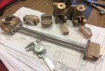
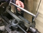
Previously I showed you how we machined down a 3" x 1" x 13" block of steel to start to form the connecting rods for the steam engine. There will be one of these for each cylinder and they are turned down with a taper. In the photos attached, you can see a completed connecting rod vs one that is still getting machined down to be tapered. To do this, the piece is offset slightly in the lathe so that it cuts at an angle (making the cut deeper on the end in the chuck). This results in one end being thinner than the other. If you look very closely, you can see the corners have started to get rounded over, ending at the current location of the cutter. Remember that these are hollow, so starting from a large block of steel, we've removed a majority of the original steel.

The second photo shows the ends that go on each of these connecting rods to join them to their respective pieces. You can see the hole that will be bored out to connect this to the crank shaft. The other end (to the right) will be bored out as well and connects to the crosshead. Above the setup of a complete rod, you can see the individual pieces that have been machined down from castings.

At the very top of the second photo, the almost completed crossheads are located. They each get two threaded holes in them yet, then they will be sanded down to be shiny. These cross heads attach to the piston rod and will move back and forth allowing the connecting rod to pivot as the crankshaft requires. See https://www.youtube.com/watch?v=R0YFwrQH58A for a video of how the engine will ultimately fit together and run.

Underneath all of the pieces you can see some of the diagrams that we are working from.
 

Attachments

  • photo255639.jpg
    photo255639.jpg
    197.2 KB · Views: 3
  • photo255640.jpg
    photo255640.jpg
    275.2 KB · Views: 3

seikeinlemming

Petty Officer 2nd Class" & 2020 Splash of the Year
Joined
May 23, 2011
Messages
140
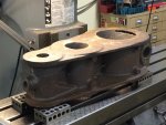
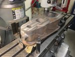
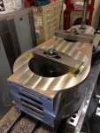
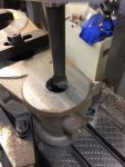
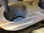
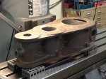
We've moved on to the cylinder block for the past 2 months. In the photos below you can see it start as a casting and moving through the different stages.


IMG_1266 (1).jpg
Above: Shows the casting as it came to me. This had to be precisely aligned down the middle of the milling machine table so that when we did our measurements for the different holes, they all were spaced correctly.


IMG_9106.JPG
Above: One side is machined level... taking off 0.015 of an inch at a time; then the entire casting is flipped over and machined to its final thickness. If you look to the back of the part (away from the camera), you will see some of the rough edge still visible as this was not the final cut. As each cut is made, gradually more and more of the casting becomes shiny as the rough edges become square and smooth.


Photo Jan 05, 4 09 34 PM.jpg
Above: This photo shows the end with all of the slots that send steam through the cylinders. They were all part of the casting so with the exception of the top and bottom grooves, I did not have to manually machine these passageways.


Photo Jan 05, 4 09 56 PM.jpg
Above: Boring the first of three holes (the smallest). Each pass takes off about 0.025 inch per pass, and takes 20-30 minutes per pass. Removing up to 1/2 of an inch required multiple 8+ hour days, setting the cutter, waiting, and then doing it all over again 30 minutes later. Quite literally a boring - boring job.


File Feb 03, 6 04 28 PM.jpeg
Above: Boring the largest of the three holes (low pressure cylinder). More so than any other location on the steam engine, these cylinders are where every thousandth of an inch matters so things run smoothly. While most of the machining on this engine we do to that level of accuracy, many places it isn't required and is practice for times like this where if you exceed the drawing by 0.001 or 0.002 inches, it can have detrimental impact to the performance of the engine.
 

Attachments

  • IMG_1266 (1).jpg
    IMG_1266 (1).jpg
    361.8 KB · Views: 4

archbuilder

Vice Admiral
Joined
Sep 12, 2009
Messages
5,697
Very interesting. So the steam passes through more than one cylinder is that correct?
 

seikeinlemming

Petty Officer 2nd Class" & 2020 Splash of the Year
Joined
May 23, 2011
Messages
140
Archbuilder - You are correct. The steam comes out of the boiler and into the valve (small hole at end of cylinder block). This valve directs the steam to one side then the other of the high pressure cylinder. As the steam is exhausted from the high pressure cylinder, it has lost some heat and pressure (and thus, energy) and is sent to the low pressure cylinder where it is reused. After this it ultimately finds its way back into the boiler (as water, after going through a condenser) to be reheated.

Having multiple cylinders makes the engine more efficient. For those that are interested, here is the wikipedia link for compound steam engines, it is very descriptive in how exactly this process works: https://en.wikipedia.org/wiki/Compound_steam_engine
 

archbuilder

Vice Admiral
Joined
Sep 12, 2009
Messages
5,697
Thanks, that is what I was thinking, but I don't know squat about steam. So what we are look at if I understand it correctly is the block that houses the cylinders. I'm assuming there separate castings for the head that caps the top side and on the bottom to hold the crank shaft? This is very cool, thanks for sharing such an unusual project with us!
 

seikeinlemming

Petty Officer 2nd Class" & 2020 Splash of the Year
Joined
May 23, 2011
Messages
140
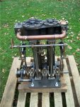
You are correct once again! The caps for each side have already been machined. There will be quite a bit of distance between the crankshaft and the cylinder block. I had posted this photo a while back, but it is relevant now, so I will post again to reference off of it. This is the same model engine as what we are building. You will see the cylinder block at the very top with two top castings, one on each cylinder. There are then lower castings that allow the piston rod to exit the cylinder with a long connecting rod (about 1 foot) down to the crankshaft at the very bottom.

You will also see the third hole which was bored out (smallest one) on the far right. There is a cover for that as well. The giant pipe running left to right is what moves the steam from one cylinder to the other to be used the second time.

image_152581.jpg
 

archbuilder

Vice Admiral
Joined
Sep 12, 2009
Messages
5,697
Ok that makes a lot more since seeing it in context. that is kind of cool how the rods and crank are exposed, should be nice to see the parts moving round. What is the stroke? I have a friend who is in the Horseless Carriage Club of America......I sometimes see things like this in his shop. I am always amazed at the craftsmanship.
 
Top