1976 Tom Boy Boat, 1976 40 HP Johnson Outboard and who knows what Trailer

mickyryan

Rear Admiral
Joined
Apr 18, 2016
Messages
4,214
dont think crimp clamps are coast guard or aba approved or you would see them on all the boats :) not saying you are gonna get in trouble but i would try to stay within spec as they know more about issues then us usually:)
 

kcassells

Fleet Admiral
Joined
Oct 16, 2012
Messages
8,737
I'm going with pex and have no issue with the applications. Using it for my supply water to the fish well/wash down from the pump/thru hull fitting. All the tru hull will be brass or bronze with the correct dialectric fittings.


Bluefin crimp fittings are compatible with PEX tubing. Crimp fittings are barbed for installation inside tubing after which a crimp ring or cinch clamp is used to hold the fitting onto the tubing.

Copper PEX rings are crimped using a Crimp Tool to an acceptable diameter then checked by a diameter Go-No-Go Gauge. Copper PEX rings are designed to go over PEX tubing to lock in barbed PEX crimp fittings onto the tubing. High quality material and manufacturing insure a tight seal over PEX tubing using a pex crimping Tool.

shopping
 

mickyryan

Rear Admiral
Joined
Apr 18, 2016
Messages
4,214
Im sure pex is probebly used in the marine industry for showers freshwater supply but id use sharkbite, fittings are plastic and what little metal is ss and esy as hell to install
 

kcassells

Fleet Admiral
Joined
Oct 16, 2012
Messages
8,737
Have had minor issues with sharkbites. They def. have a place to be used but I just don't like burying them. OK exposed.
 

kcassells

Fleet Admiral
Joined
Oct 16, 2012
Messages
8,737
I'll stick to the pvc fittings and da ring. Only for the little runs of pipe. With a blow out. Everything else, bronzey brass. threaded in the splashwell area. Sorry gm for the hijack.
 

gm280

Supreme Mariner
Joined
Jun 26, 2011
Messages
14,605
Ha any time I can drum up conversation about how everybody does their setup, that is a good thing. Ideas are what this site is all about...I think.

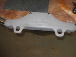
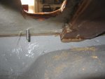
I did get some more things worked out today. I am installing the front Tom Boy Boat plate and of course the rub rails. Since the front now has a deck installed different then the original design, I can't use the usual pop rivet attachment procedures.Those will work for the sides. I had to go to both threaded bolts and wood screws. But I ran into a little situation now that I have to solve. The long threaded stainless steel bolts go in okay, but they are actually threading into a brace that runs front to back of the deck. And while I can see them, I have to figure out some way to grind the wood around them enough so that the stainless lock nuts and washer can fit on them. And of course, the area is very tight and not easily accessible. But I think I have a plan... I think I can cut and grind enough to allow the flat washer and lock nut go on. We will see.

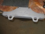
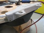
The first picture is the Tom Bot Boat aluminum plate. It has to go back on because it joins the two side rub rails at the front. I have it primed now, but not finished painted. I was going to try and polish it to a mirror finish to accent the rub rails, but the porosity is so bad that I can't get a decent finish. So prime fill and prime again and paint is the fix for that. The second picture showed the threaded bolt coming through. It is on the right side in that piece of wood. You can see it just a little. So I either grind and cut it open enough for the washer and nut or don't use it. And that is not the answer.
 

Attachments

  • photo302290.jpg
    photo302290.jpg
    60.6 KB · Views: 0
  • photo302291.jpg
    photo302291.jpg
    70.2 KB · Views: 0

gm280

Supreme Mariner
Joined
Jun 26, 2011
Messages
14,605
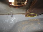
I got an idea and am post it here to see what you all think. In the new picture attached, the oval area is where that bolt is coming through. I though about using a long extension, because of the tight area, and use a forstner bit (3/4" or a little larger) to cut a flat larger enough to get the washer and bolt installed. Think that will work? It would give me a fairly flat bottom surface to tighten against... :noidea:

I can even apply some poly coat over the fresh wood area as well. :confused:
 

Attachments

  • photo302292.jpg
    photo302292.jpg
    34.6 KB · Views: 0

sphelps

Supreme Mariner
Joined
Nov 16, 2011
Messages
11,468
As long as you can get the drill in there sounds like a plan to me ..
 

gm280

Supreme Mariner
Joined
Jun 26, 2011
Messages
14,605
The way the front is designs, I have a pretty good opening to at least get a loonnnggg forstner drill setup into the place with ease. So I will try to do that. And yes, it is pretty much like counter sinking but with a flat bottom via the drill bit design. But it that works, and I think it will, that should fix that issue and I can more on. I will have to do that with the other side as well. Those bolt come in from the front vertical edge of that Tom Boy aluminum plate with two more coming down from the top (you can see one in the picture) of that plate. But once I get that worked out, I will remove the plate and finish painting it and install the carpet on the deck. I'll post the results later on.
 

gm280

Supreme Mariner
Joined
Jun 26, 2011
Messages
14,605
Well like the saying goes, where there is a will, there is a way. However not the way I initially thought. I was pretty excited to get those bolts fitted today and after a morning of weeding one of the islands in the yard where the ants had a fest on my hands, I started on the boat again.

But the extension I was talking about to reach the bolt holes wasn't albel to fit any of the forstner bits. Those bits are about 3/8" shanks and the extension only accepted 1/4". I thought maybe I could chuck one up in the metal lathe and turn it down. And a little voice say NOOOOOOO........

Then I thought I also have a flexible extension. Well that too only accepted 1/4" bits max. So looking at the tight area, I thought maybe I could chuck the forstner bit in teh DeWalt cordless drill and try to get in there. Well I was able to do that, but the bit really wasn't cutting like planned, go figure. So thinking about what to do next, I thought maybe a wood gouge for turning wood on the wood lathe would work. Sounded good in my head, but another no go in reality.

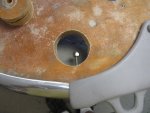
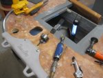
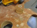
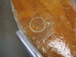
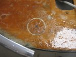
Then on to some 3M 2" flapper disks, with miserable results. This was going to be a lot harder then I really thought. As I tried different things, It dawned on me, why don't you just drill a hole through the top with a 2" or so hole saw. WALA I lined it up fairly close to where the bolt came though and drill it out. There was that answer. I realize I have to reseal that up, but that is peanuts in comparison to every other idea.

I drill two 2" holes though the top and was able to fit the bolts and even cut them down to a more sizable length. I also cut the other top bolts that came in from the top to their proper length as well. Deburred all of them and made sure the washers and nut would fit without any problems just in case I ever have to remove them down the road.

So that problem is finished now and I am going for carpet to that front deck next before installed the remainder of the rub rails. But that will be easy since all I have to do is drill the holes and pop the rivets on. I have total access from both sides to do that.

None of the bolts were tighten up at this time. just fitted in to check they would fit.

Until next time, you all have the best day ever!
 

Attachments

  • photo302290.jpg
    photo302290.jpg
    60.6 KB · Views: 1
  • photo302340.jpg
    photo302340.jpg
    79.3 KB · Views: 1
  • photo302341.jpg
    photo302341.jpg
    80.5 KB · Views: 1
  • photo302342.jpg
    photo302342.jpg
    85.8 KB · Views: 1
  • photo302343.jpg
    photo302343.jpg
    59.6 KB · Views: 1

oldrem

Commander
Joined
Nov 7, 2013
Messages
2,002
Nice job of re engineering on the fly! Amazing what we can do when plans A B and C fail us :)
 

gm280

Supreme Mariner
Joined
Jun 26, 2011
Messages
14,605
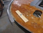
Well that plan of drilling through the top deck seems to work well. I mixed up some poly, MEKP and Cabosil and made a paste like glue to reinstall those cut out hole plugs back in. But I only used about a 1/4" of the cut out plugs. I cut the rest off using the band saw. And to keep them from going in too far, I used a flat piece of wood with a hole drilled in it to lay on top with a bolt through the plug to keep it secure until the glue cured. Then I removed the flat wood and bolt(s) and sanded the surface smooth again and mixed up some poly and CSM to re-waterproof those areas. That problem fixed. .

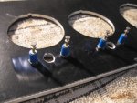
I then switch my attentions (what little I still have) to the multiple control panels to get them ready to install. However, I looked them over and thought a more solid configuration was to install two small standoffs to wire the LED indicators to before wiring them in the circuits. That was a little doing but I got them installed as well.

I will post pictures soon while I mentally think how I need to sort all the wires out and which ones need a buss block setup.

So little by little it is getting done. The little things though really add up.

You all have a nice day...
 

gm280

Supreme Mariner
Joined
Jun 26, 2011
Messages
14,605
I little bit each day is how you get it done!

Yes and some times that is all I get done is a LITTLE BIT. But I am trying to do something everyday to get this finished. And I gain more interest each day as things are getting accomplished.

Here are some pictures of what I was talking about with the cut out hole being resealed. I needed to make sure the hole plugs would not settle in too far and block the bolts coming in from the front, so I used the wood trick and a bolt to hole them flush with the top of the deck. And since the bolt holes are about an inch below, it worked out great. The hole plugs were cut down to about 1/4". I can now bolt that front Tom Boy plate on without any problems. And that Tom Boy plate connects everything together with the rub-rails and front part of the boat.

As for the standoffs, I am used both some 12 volt indicator LED lights and simple 3mm LEDs separately. But I have to connect them to the wiring circuits. Since the little wires coming off the LEDs are very thin, I decide to install standoff to connect the LEDs (and current control resistors) to and then I can use whatever method I need to wire them into their appropriate circuits. The pictures show how I set them up. I drilled some 7/64" holes for some 4-40 stainless steel counter sung screws from the front aluminum plate so the cover plates would fit without and obstruction. Seems to work pretty good and it helps hold the fragile wires on those LEDs.

So a little more progress. I only have to think how I need to install some small unique one-off designed PC board that support the panels yet. And all the panels will be finished. And that means I can start buss baring the wires.

You all have a fantastic day...
 

Attachments

  • photo302630.jpg
    photo302630.jpg
    90.4 KB · Views: 0
  • photo302631.jpg
    photo302631.jpg
    107 KB · Views: 0
  • photo302632.jpg
    photo302632.jpg
    81.3 KB · Views: 0
  • photo302633.jpg
    photo302633.jpg
    89.1 KB · Views: 1
  • photo302634.jpg
    photo302634.jpg
    62 KB · Views: 1
  • photo302635.jpg
    photo302635.jpg
    74.6 KB · Views: 1

Woodonglass

Supreme Mariner
Joined
Dec 29, 2009
Messages
25,928
GM Please refresh my memory on how you make your instrument panels look Soooooo GREAT!!!
 

gm280

Supreme Mariner
Joined
Jun 26, 2011
Messages
14,605
GM Please refresh my memory on how you make your instrument panels look Soooooo GREAT!!!

Sure WOG. It is really not as difficult as you may think. Otherwise I wouldn't be able to do it.

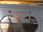
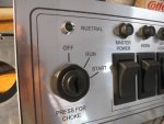
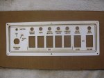
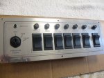
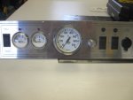
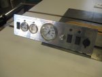
I first measure the place I want to install a panel. Then I design the panel using a program called Visio. It is a program usually used to layout office plans and flow charts. But since I didn't have any other program, I used it for other things and designs for my plates. Now I know some will think they are not going to buy such a program to do theirs. And you really don't have to either. And design software will suffice. After you design your panel you are going to either take it to a trophy shop or if you have the equipment, use your own LASER engraver. Most trophy shops can easily product your designs on whatever you like for your panel. The colors, shapes and materials are near endless.

I just happen to own a commercial large bed LASER engraver. So I transfer my designs from Visio to Corel Draw. Corel Draw is a program that converts the Visio design into a Raster and Vector program that the LASER engraver uses to LASER the panel. There are lots of programs you can use to design your panel. But all of them has to be transferred to Corel Draw to LASER engrave. And of course you can also use Corel Draw to make you design and skip the transfer. Your call on that. I just know Visio inside and out and that is why I use that program.

After you LASER engraver your cover panel, the you can use it like that or make a aluminum backer plate to stiffen it up. That is what I do. The LASER panel is merely a plastic laminate that gets glued or attached to eh backer plate to give it strength and make it solid. But depending on the laminate you choose, you don't need a backer plate. I was using what we had available at the time and since it as a thin material, I made backer plates.

And that is my process for those plates. As for the designs, it is entirely up to your ideas and imagination. before I retired, I use to design lots of panels for all types of applications for commercial use and aircraft as well. I just design things like I like to see them.

Hope that works for you. And remember you can use any program to layout your design, and then take that design to a trophy shop and they can do the rest.
 

Attachments

  • photo302664.jpg
    photo302664.jpg
    79 KB · Views: 0
  • photo302665.jpg
    photo302665.jpg
    73.7 KB · Views: 0
  • photo302666.jpg
    photo302666.jpg
    175.7 KB · Views: 0
  • photo302667.jpg
    photo302667.jpg
    82.6 KB · Views: 0
  • photo302669.jpg
    photo302669.jpg
    109.3 KB · Views: 0
  • photo302670.jpg
    photo302670.jpg
    315.1 KB · Views: 0
  • photo302671.jpg
    photo302671.jpg
    52.5 KB · Views: 0
  • photo302672.jpg
    photo302672.jpg
    54.3 KB · Views: 0
Top