Hey SHSU,Slow and steady wins the race. Mine took 2 1/2 years and I told the Admiral 6 months max.... lol
SHSU
Its going to be a tank!!!Hey SHSU,
I'm just over four years and hoping to splash her in two and half weeks! That is about as slow as it gets...
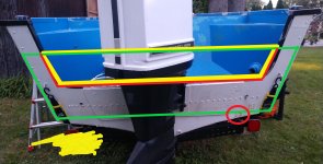
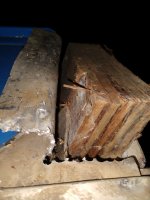
If I understand your plan correctly the yellow piece would be butt welded and overlapped with the green.Also, I have a plan for how I want to rebuild the transom as a 25inch. The yellow would be a piece of aluminum welded where the red lines are to the existing transom skin. Then the green is a second piece of aluminum that is buttered on with 5200 to fill the existing holes. View attachment 351344
Going to send this to a welder for a quote, any ballpark tips on what would be fair price?
I’m not so sure...I’m in the forever club too.Hey SHSU,
I'm just over four years and hoping to splash her in two and half weeks! That is about as slow as it gets...
I’m late to the party. Will you be putting an extension on the lower unit of your motor or swapping?Also, I have a plan for how I want to rebuild the transom as a 25inch. The yellow would be a piece of aluminum welded where the red lines are to the existing transom skin. Then the green is a second piece of aluminum that is buttered on with 5200 to fill the existing holes. View attachment 351344
Going to send this to a welder for a quote, any ballpark tips on what would be fair price?
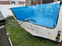
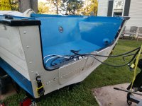
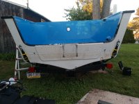
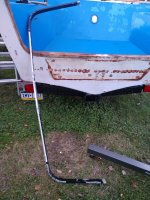
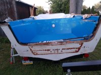
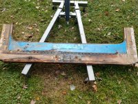
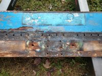
To SHSU about the knee brace, it has already been customized by the PO with a long L bracket that is most of the length of the transom. I plan to not modify that further if it feels solid. You can see the row of bolts on the outside if the transom in the previous pic.View attachment 351572
I am however looking for ways to modify the splash well, as I would like to similarly raise the drain holes that are in the transom about 5 inches. and the splash well would need to match that. I also feel that having that bottom of the splash well raised would add some of the additional stiffness higher up on the transom wood piece that would be needed with this mod.
Thanks for the discussion on this one, I very much appreciate all the advice and commentary on my project from those who have already built a boat and watched other builds on this forum.
I like the idea of the L bracket, but I don't believe it transfers much to your knee brace if you raise the transom height. So the force associated with the motor wont be transferred appropriately. That is just my simple mind, not an engineer here.To SHSU about the knee brace, it has already been customized by the PO with a long L bracket that is most of the length of the transom. I plan to not modify that further if it feels solid. You can see the row of bolts on the outside if the transom in the previous pic.
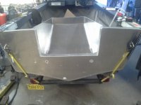
I had a custom splashwell made for mine and moved my drain holes as well. I had my welder weld the old holes closed with the pieces I cut out from their new location. I had to do a lot of measuring prior as you obviously can't have the transom in place during install. So I figured out where I wanted them and then used that to figure out my splashwell size.I am however looking for ways to modify the splash well, as I would like to similarly raise the drain holes that are in the transom about 5 inches. and the splash well would need to match that. I also feel that having that bottom of the splash well raised would add some of the additional stiffness higher up on the transom wood piece that would be needed with this mod.
Here is a splash well of 1/4"
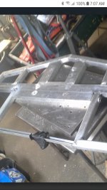
A 2×4" tube bolts on with 3 attachment points to convert from 21" to 25" shaft
Has been working well in large ocean swells while drifting
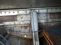
This is from the construction phase. You can see both the long and x long shaft bolt pattern in the picture. This pic was in my build thread. I will add some with the x long motor mounted to my thread.Interesting, any pictures of the tube in place?
SHSU
That makes more sense. I imagined an external tube being bolted on. Looks good though and wont decompose over time.This is from the construction phase. You can see both the long and x long shaft bolt pattern in the picture. This pic was in my build thread. I will add some with the x long motor mounted to my thread.
Sometimes I don't describe things properly. The 2x4" tube was capped on the ends by welding 3/4" or 1" plate in and it was threaded for 1/2" bolts. Between the bolts in the center another insert is welded inside and threaded 1/2" with the bolt installed from the bottom.That makes more sense. I imagined an external tube being bolted on. Looks good though and wont decompose over time.
SHSU