Restoring a 1990 Larson

Meames1

Petty Officer 2nd Class
Joined
Dec 14, 2020
Messages
157
Hello,
First time poster, been lurking and learning for some time. Sorry for my first post being so long winded.
This fall we purchased our first boat ! It's a 1990 Larson 210 DC. I bought it from the second owner who bought it from the original owners and quickly realized he was over his head. The boat was listed as having a bad head gasket (4.3 V6), but I figured a crack and expected the engine to be junk. During inspection I found a few soft spots on the floor and fully expected rotted floors, stringers, bulkheads, etc. After purchase for basically what the Shorelander dual axle trailer was worth, I own it. Any visions of the wood being OK were quickly derailed during the 30 mile tow home. I've towed a ton of trailers and race cars in my life and this 3,000lb boat "felt" more like 5K lbs behind the truck. I knew it was water logged.
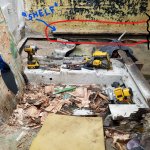
So, I dove in head first, tore everything out and getting ready to start the installation of new wood/glass. I have done a fair amount of glass work and I'm not too concerned about my ability especially after reading all the posts and advice on here. I do have a few questions and I'm sure many more will come as I progress. Please be patient as I'm unfamiliar with a lot of the terminology in the boating world.
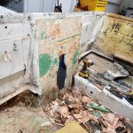
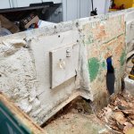
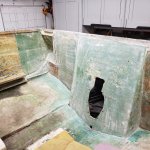
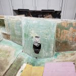
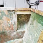
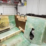
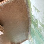
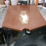
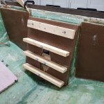
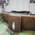
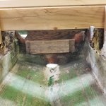
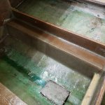
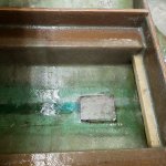
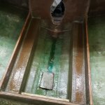
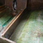
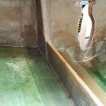
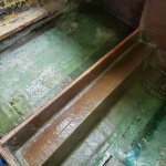
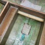
I expected the stringers and bulkheads to be rotten which they were, but I was hoping the transom was OK......a poke test at he bottom showed some rot, so I went ahead and tore it out too. Another reason to tear out the transom was I didn't like the way it was built. Trust me when I say I don't think I'm smarter than Larson, but I do fabricate entire racecars for fun, so I've seen a thing or two about strength etc. The transom consisted of a base layer of plywood laminated into the fiberglass with a second layer only partially as big as the first stapled to it. The two pieces were not even laminated together. This was in the "center" of the boat @ the keyhole and only about 2' wide. The second part of the rear of the boat stepped back and only had one 1/2" ply laminated to the glass with one 3/4" each side about 12"x8" stapled to the base ply to support the tie-down loops. Then in the top rear corners there is a section of the hull that sticks out about 8-10" (admittedly I have no idea what these are called or what their function is), these were just filled with rigid foam and a light coat of resin and chopped strand sprayed over them and a light gel coat.
So, here is my plan for the transom going back. Please feel free to jump in and advise me if I'm doing wrong. Thanks in advance, I'm sure I'll have lots of questions.
Oh, BTW I'm installing a 350 mag in place of the V-6.
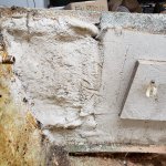
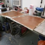
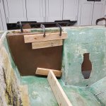
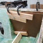
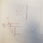
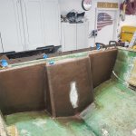
Obviously start with 2, 3/4" pieces of plywood glued together and glassed to the center of the transom, following methods seen in these threads. (I'll be using poly resin, 1.5oz csm, and 1708 etc.) The "outer sections of the transom I will install one layer of 3/4" (up from factory 1/2") and extend it all the way to the hull at full height, covering the two kick outs at the top rear of each side. I will go back when foaming the floors and foam these two kick outs also. Then on each side of the transom there are two triangle shaped area's that the factory added no wood, it's just fiberglass. I would like to fill these areas with a 3/4" ply PB'd in , tabbed, and then laminate the entire transom with the last layer of 1708. I plan on making it as smooth as possible including the floors and gelcoating as I don't want carpet, or at the most snap-in carpet that we can remove and clean.
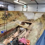
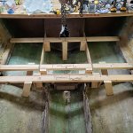
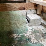
One question, you'll see the entire hull was spray-foamed with roughly 1" of foam and then some "apparently" sprayed fine chop and resin. I had to cut portions of this out be able to do the required tabbing. Was this foam there for strength, or noise reduction (both)? Do you think I should try and replicate this when done ?
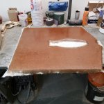
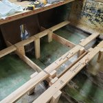
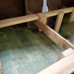
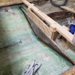
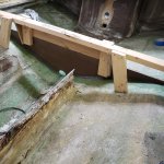
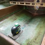
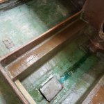
On to the pics. I'll try and get more as I go, didn't get many pre-demo.
 

Attachments

  • 20201228_191633.jpg
    20201228_191633.jpg
    1.4 MB · Views: 95
  • 20201228_191640.jpg
    20201228_191640.jpg
    6.7 MB · Views: 98
  • 20201228_191648.jpg
    20201228_191648.jpg
    6 MB · Views: 92
  • 20201228_191651.jpg
    20201228_191651.jpg
    1.4 MB · Views: 87
  • 20210104_191442.jpg
    20210104_191442.jpg
    6.3 MB · Views: 86
  • 20210104_191458.jpg
    20210104_191458.jpg
    6.2 MB · Views: 85
  • 20210104_191438.jpg
    20210104_191438.jpg
    6.2 MB · Views: 94

JASinIL2006

Vice Admiral
Joined
Feb 10, 2012
Messages
5,548
Have you read the thread on the rebuild of an '87 Larson DC-215 by @sms986 ? His boat and yours have somewhat different construction at the stern, but you might find some useful stuff in his highly detailed account.

Nothing wrong with using two sheets of 3/4" plywood at the transom, so long as your total thickness at the keyhole stays between 2" and 2.25" (including all layers of fiberglass) - assuming you have a Mercruiser outdrive. My Larson, while generally a heavy and decently built hull, also had some head scratchers... for example, the two pieces of plywood in the transom were not glued or laminated together; they were held together by staples and the tabbing around the edges. There is no harm in putting it back together better than you found it.

I'll be interested in what others think, but for the foam-filled pockets near the corners of stern, I'd be inclined to fill them with foam, shave it down so it's level with the adjacent transom and then run plywood over that whole section.

Finally, it's not a bad idea to create a 'signature' block that gets attached to all your posts; see mine below and check out some from other members, too. It makes it easier for us to know what you're working on, so we can give better feedback.
 

Meames1

Petty Officer 2nd Class
Joined
Dec 14, 2020
Messages
157
JASinIL2006,
Thank You, replies in order.

Yes, I've seen the '87 Larson thread, very informative.

Yes, Mercruiser power. Alpha 1 drive. The transom glass is 3/8" thick, so with the 2 pieces of 3/4" I should be right around 1 7/8" with the mat making up the balance so I "think" I'll be good. I'll continuously measure as I'm adding layers.

I was thinking of running the plywood first and then cutting a hole near the top and foaming it in place similar to doing the floor. Interested in seeing what others think.

Thanks, Noted.
 

sms986

Petty Officer 1st Class
Joined
Sep 18, 2017
Messages
334
Hey hey, glad I was tagged in this.

My transom was the same. I think about 1 1/4" or so of plywood covered the whole thing then there was a 1/2" sheet that was just a small square around the keyhole. It was stapled on and taped at the top and bottom. Actually what started it all was when that separated from the rest of the transom. I went ahead and did 2 3/4" sheets and a 1/2" sheet across the whole transom, pb'd together. Outer skin was 1/4" thick and I did 2 layers of 17 oz on the inside plus 2 layers of tabbing around the edges to put it in.
 

JASinIL2006

Vice Admiral
Joined
Feb 10, 2012
Messages
5,548
Hey hey, glad I was tagged in this.

My transom was the same. I think about 1 1/4" or so of plywood covered the whole thing then there was a 1/2" sheet that was just a small square around the keyhole. It was stapled on and taped at the top and bottom. Actually what started it all was when that separated from the rest of the transom. I went ahead and did 2 3/4" sheets and a 1/2" sheet across the whole transom, pb'd together. Outer skin was 1/4" thick and I did 2 layers of 17 oz on the inside plus 2 layers of tabbing around the edges to put it in.

You're the expert now... gotta help this guy!
 

Meames1

Petty Officer 2nd Class
Joined
Dec 14, 2020
Messages
157
Productive weekend. Got all the transom wood fabricated, coated both sides, and 1 layer CSM. The "outer" two pieces are a single piece of 3/4" MDO, up from the factory 1/2" in this area. The center keyhole area of the transom is two pieces of 3/4" MOD glued with Gorilla waterproof "Ultimate" adhesive.
Adhered one side of the outer transom in as a test. First time mixing PB, I was pretty happy to have enough but not any waste. I plan on adhering all the pieces before I go back and do the PB fillets. Hope to have the entire transom tabbed and finished with the 1708 by then end of next weekend.
 

Attachments

  • 20210109_124816.jpg
    20210109_124816.jpg
    6 MB · Views: 48
  • 20210110_114057.jpg
    20210110_114057.jpg
    6 MB · Views: 45
  • 20210110_171319.jpg
    20210110_171319.jpg
    1.8 MB · Views: 47
  • 20210110_171347.jpg
    20210110_171347.jpg
    5.8 MB · Views: 48

Meames1

Petty Officer 2nd Class
Joined
Dec 14, 2020
Messages
157
Got the other side transom piece adhered in and had enough PB left to do some of the fillets along the bottom and side.
Also had time to add a layer of CSM to the bottom edges of the transom and a layer of 1708 on the inside face. I wanted the first time I installed 1708 to be on a horizontal surface and I'm glad I did, a bit of a learning curve. I'm gonna try and wet the csm layer of the 1708 first next time like poster @todhunter is doing. One reason this forum is so useful.
If all goes well, transom gets adhered tomorrow after work.
 

Attachments

  • 20210111_192523.jpg
    20210111_192523.jpg
    1.6 MB · Views: 41
  • 20210111_192515.jpg
    20210111_192515.jpg
    1.5 MB · Views: 41
  • 20210111_180938.jpg
    20210111_180938.jpg
    812.8 KB · Views: 40
Last edited:

Meames1

Petty Officer 2nd Class
Joined
Dec 14, 2020
Messages
157
OK, I'm looking for a little advice from the group. I hope I can explain this right. My boat has two "shelfs", or compartment bottoms that are glassed into the sides of the hull around 6-8' long. The purpose (or at least main purpose) of these is that they make up the bottom of the integrated storage pockets that run along the gunnels from the helm to the rear seats @ the transom. These are approximately 1" thick and 4" wide. They are glassed to the hull and very sturdy. I'm 260lbs and can stand on them (obviously I don't, but hopefully you get the picture.
The problem is, the floor attaches to the hull only about 3" under these "shelfs" lets call them. I'm worried when it's time to tab the new floors in I'll have two issues, #1 the new tabbing will only go up the hull a few inches, and #2 the difficulty tabbing in a such a small area under these.
I've attached some pictures that hopefully helps to understand what I'm saying.
I'm thinking about running the new floor to the hull as usual and attach with PB. Then adding an additional vertical piece from the new floor to the shelf again with PB. Basically closing-in the shelf area to floor. Then I will be able to tab several inches up the hull and down the shelf and onto the new flooring. The existing shelf stops about 12" from the transom and basically about 12" from the helm. I would extend the stern end of the shelf to the transom and taper the front edge to the area next to the helm as the floor also tapers to the bow at this point. Finally, I would cut a few circles in the shelf and fill the cavity with foam when I do the floors.
I really don't want to remove these shelfs and re-glass them later, plus I'm unsure if they also are designed to lend support to the hull.
Please see pics and my rough drawing, hopefully I explained everything correctly. Comments ??? TIA !
 

Attachments

  • Inked20201228_191643_LI.jpg
    Inked20201228_191643_LI.jpg
    3.5 MB · Views: 43
  • 20210112_101911.jpg
    20210112_101911.jpg
    275.1 KB · Views: 42

Meames1

Petty Officer 2nd Class
Joined
Dec 14, 2020
Messages
157
Transom complete other than drilling holes for stern drive and slotting for steering shaft. Also need to add a little more PB at the top to even it out, but I'll wait until the next time I have to mix some. I installed 3/4" side pieces where the original design had none. Everything tabbed and reinforced.
 

Attachments

  • 20210113_191203.jpg
    20210113_191203.jpg
    1.7 MB · Views: 50
  • 20210117_133057.jpg
    20210117_133057.jpg
    4.9 MB · Views: 51
  • 20210117_133129.jpg
    20210117_133129.jpg
    5.7 MB · Views: 50

Meames1

Petty Officer 2nd Class
Joined
Dec 14, 2020
Messages
157
Spent the last 2 nights building jigs to locate and adhere the Bulkhead and rear stringers that are part of the engine mounts.
Now, to remove them and tear out the rest of the stringers and bulkhead. More grinding. The jigs will allow me to adhere the pieces at the finish height instead of cutting them down after.
The goal is to have the rear bulkhead, rear stringers, and engine mounts built, installed, and tabbed by the end of the month.
 

Attachments

  • 20210119_195136.jpg
    20210119_195136.jpg
    6.1 MB · Views: 49
  • 20210119_195232.jpg
    20210119_195232.jpg
    6.2 MB · Views: 46
  • 20210119_195214.jpg
    20210119_195214.jpg
    5.6 MB · Views: 44
  • 20210119_195147.jpg
    20210119_195147.jpg
    6 MB · Views: 44
  • 20210119_195201.jpg
    20210119_195201.jpg
    6 MB · Views: 48

Meames1

Petty Officer 2nd Class
Joined
Dec 14, 2020
Messages
157
Got the rear bulkhead in. Not as much accomplished this weekend as I had hoped. I'm using a different poly supplier than when I did the transom and the new stuff takes a fair amount longer to cure, so I'm getting used to what I can do with it. Coated both sides of bulkhead, first with just resin so the wood could soak it up and let it sit overnight. Then added a layer of CSM and a layer of 1708 before gluing it into the boat with PB.
Jig worked great. Up next, install the rear stringers to transom and start building the engine mounts.
 

Attachments

  • 20210124_153146.jpg
    20210124_153146.jpg
    6.8 MB · Views: 37
  • 20210124_153116.jpg
    20210124_153116.jpg
    6.2 MB · Views: 36

Meames1

Petty Officer 2nd Class
Joined
Dec 14, 2020
Messages
157
Looking for opinions. The gas tank originally had a 1/2" plywood and glass cover the full length that has an extruded aluminum edge and is fastened to the stringers with screws. This obviously allows any water to seep down around the tank and ultimately to the bilge. Not to mention the screws into the top of the stringers.
Thinking ahead, I'm thinking of completely glassing it in and installing a deck plate over the sending unit for future access if needed. With the major downside being the necessity of cutting the floor panel back out if I ever need to remove the fuel tank for some reason. Thoughts ?

Meanwhile, I have the rear stringers in and currently building the engine mounts. Still on track to finish the aft section, stringers, engine mounts, and all tabbing by the end of this weekend. Pics soon, haven't taken any lately been busy slingin glass. :giggle:
 

JASinIL2006

Vice Admiral
Joined
Feb 10, 2012
Messages
5,548
I did exactly as you propose. I figure, if I have to cut and pull up the deck over the fuel tank, I can just glass it back in after I'm done. No worries about water intrusion, except via the deck plate.
 

todhunter

Canoeist
Joined
Sep 15, 2020
Messages
1,244
You should be good as far as regulations go. You only need to have access to the sending unit and fittings, and the ability to inspect/remove/replace the hose between the tank and engine without having to cut the floor out.

I totally agree - I'm looking to avoid running any screws into the stringers if possible. On my boat, the tank is in the bow, and if it's gotta come out, I've gotta pull the cap off and cut out a piece of deck. o_O Hope I don't ever have to go down that road after I get it back together.
 

Meames1

Petty Officer 2nd Class
Joined
Dec 14, 2020
Messages
157
Coming along after a busy weekend. I got the engine mounts built, installed, and tabbed with 2 layers of 1708 on the bilge-side. Still have tabbing to do on the other side of the stringers tonight after work. Also, my engine mounts have a 1" raised section 14" long where the engine mounts sit. I'm going to add this on top of the completed and tabbed mount. I did it that way as I thought it would be easier to tab the mount without all the angle changes. I'll simply add this piece and tab it to the completed mount.

Additionally, for anyone looking into where to buy materials. I originally placed a large order from US Composites right around Xmas but they were closed until after the first of the year. So in the meantime I placed a smaller order from a different composite supplier on Amazon. I had been struggling a bit with laying down the Amazon supplier's 1708. Not so much with the layup, but was pulling the stitching thread out and getting really rough edges where it had been cut with the shears.
Well, I ran out of the 10 yds from Amazon and got out my 15yds I bought from US to continue on. What a Difference ! The 1708 from US Composites is much easier to work with, bends corners easier, and doesn't fray near as much where it has been cut.

Here is the only picture I have for now. This was setting up where the engine mount goes. I'll get some completed pics tonight. I built the mount similar to the factory set up. 3 layers of 3/4" plywood top / body, with a single 3/4" layer vertical brace. Then it has the 14" long section that sits 1" higher making the mounting area for the engine mount 3 1/4" thick not including the poly and mat.
 

Attachments

  • 20210129_174659.jpg
    20210129_174659.jpg
    6.1 MB · Views: 39

Meames1

Petty Officer 2nd Class
Joined
Dec 14, 2020
Messages
157
Got the the outsides of the rear stringers tabbed tonight. The only thing left on the mounts is to add 1 more piece of 1708 from the top of the stringer down over the mount and onto the lower vertical. Then a few odds and ends, adding cleats, and capping the stringers and the rear section is done. Minus the floor of course, lol.
Really burning through materials now, the PB and tabbing sucks up the resin.
 

Attachments

  • 20210201_172649.jpg
    20210201_172649.jpg
    4.6 MB · Views: 52
  • 20210201_172658.jpg
    20210201_172658.jpg
    6.2 MB · Views: 51
  • 20210201_172718.jpg
    20210201_172718.jpg
    6.5 MB · Views: 55
  • 20210201_172741.jpg
    20210201_172741.jpg
    6.2 MB · Views: 54
  • 20210201_194750.jpg
    20210201_194750.jpg
    5.3 MB · Views: 55
  • 20210201_194852.jpg
    20210201_194852.jpg
    6.5 MB · Views: 51
  • 20210201_194848.jpg
    20210201_194848.jpg
    6.4 MB · Views: 49
  • 20210201_194858.jpg
    20210201_194858.jpg
    6.8 MB · Views: 53
Top