72 Thunderbird Formula w/twin 165hp Mercs

Mark72233

Ensign
Joined
Jul 11, 2014
Messages
926
And of course the above question goes out to everyone.

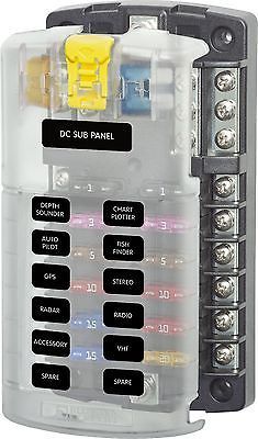
Arch the fuse block is a Blue Sea 5026.
Rated up to 32 volts DC, 30 Amps per circuit, 100 amps total per block.
 

archbuilder

Vice Admiral
Joined
Sep 12, 2009
Messages
5,697
I was just wondering mark, typically you want your circuit breaker to be a smaller amperage than the fuse box and the wire going from the breaker to the box.
 

Mark72233

Ensign
Joined
Jul 11, 2014
Messages
926
Ok Arch than that 50 or a 40 amp breaker should work. Any thoughts on the other electrical questions.
 

Mark72233

Ensign
Joined
Jul 11, 2014
Messages
926
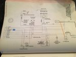
I took today off from work to get this boats electrical system put together and I am not getting very far. I pulled out my old gauge cluster since I saved it. It is still like it was when I unplugged it from the boat 2 years ago. I can't use this part because some of the wires are melted or corroded but it shows me where wires went at least at that time with that wire harness. Remember I had to rebuild both wire harnesses. Any way the old volt gauge was an Amp gauge and has three spots for wires. Ground, S and I. The new gauge is a volt gauge and only has ground and +. See pics.
 

Mark72233

Ensign
Joined
Jul 11, 2014
Messages
926
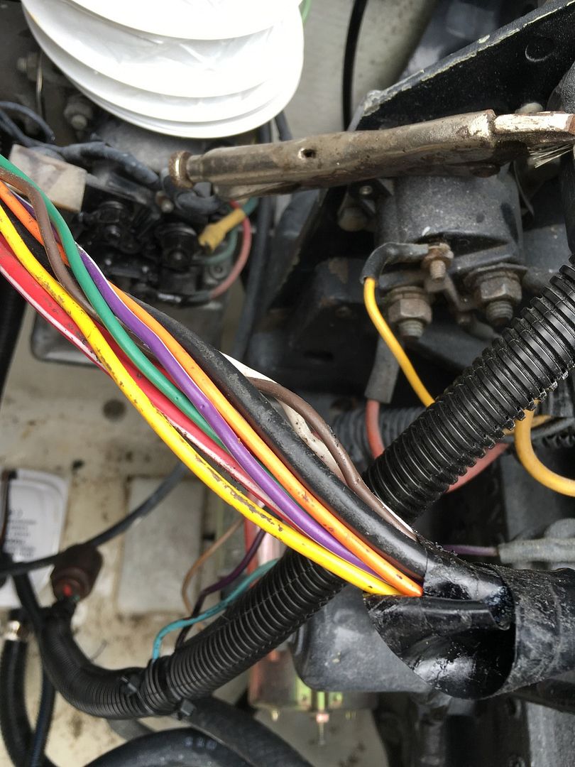
Here are the color of wires I have and where they are on engine. Green from water temp. Yellow attached to a solenoid just above the starter. Red positive starter. Red with white stripe from the alternator. Purple from side of oil pressure sensor. Orange from end of oil pressure sensor. Black from engine ground. White goes to positive side of coil. Brown attached to positive side of coil also and has a short brown wire running off of it near rear of engine that is not connected to anything but I think this is the wire that goes to a shift interrupter on the transom at the shift cable. Ok on the helm side I have the green wire connected to water temp gauge. That's as far as I have gotten😡😫😤😭💩
 

Mark72233

Ensign
Joined
Jul 11, 2014
Messages
926
I guess everyone is still at work or maybe I need to start a thread on this in Mercruiser or electrical. I still am at a stand still and have been most of the day. I checked both engines and wire color and origin from the engines are the same as back in previous post #945.
 

alldodge

Moderator
Staff member
Joined
Mar 8, 2009
Messages
42,292
AllDodge we talked some about wire colors and either running the ignition wire to the hour meter or the purple wire. I ran a wire from the ignition switch. Now onto the other wires and gauges. I have a purple wire and an orange wire both come off the what I am assuming is the oil pressure sender. See below pictures.

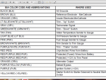
Sorry but been out all day. The purple wire previously mentioned previously was thinking that you would be using a Mercruiser hiring harness, or using the color code Merc uses. Here is Merc color chart
Merc Color Codes.png

Purple is a switch color from the key. The pic about the two wires on the oil pressure sender (orange) should be Light Blue which goes to the gauge. The oil pressure switch with the purple wire should be Tan/Blue. Manual 3 states to add it run from the purple wire (switched 12V) to buzzer, then a Tan/Blue wire to the switch. Looks like someone just run purple all the way

tan.jpg
original I6 did not always come with the buzzer, it was an add on.

And I have three 10 gauge wires also, black, red and red with a white stripe. Red with white stripe is coming from alternator. Where do these wires go. I love electrical. .

The Red/wht should be treated as orange and it goes from the ALT to the Starter terminal and normally via a 90 amp fuse mounted to the starter stud. Black is ground and Red is normally direct from the Battery.

Amp meters are installed inline between the ALT output and the battery. Many use a shunt to bypass, your setup will not use it so disregard
 
Last edited:

archbuilder

Vice Admiral
Joined
Sep 12, 2009
Messages
5,697
Mark,

The volts usually just takes a power wire from the ignition and ground. The amp gauge usually takes a hot from the battery and one coming out of the alternator, plus the ground. So basically they are wired different

Is the sending unit for the oil just above and forward of the starter? the fat round one looks like the pressure sending unit. It also looks like you might low pressure switch? I think there is only one wire from the pressure sending unit.

I may have missed it, but is the wiring harness you are using bundled up? you may need to run a few new wires or terminate in the case of the Amp and Volt gauges. Do you have an Ohm meter? Helps to track down where wires go sometimes.
 

Mark72233

Ensign
Joined
Jul 11, 2014
Messages
926
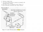
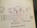
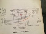
These are pictures from the Merc manual that covers my year Merc 165hp.


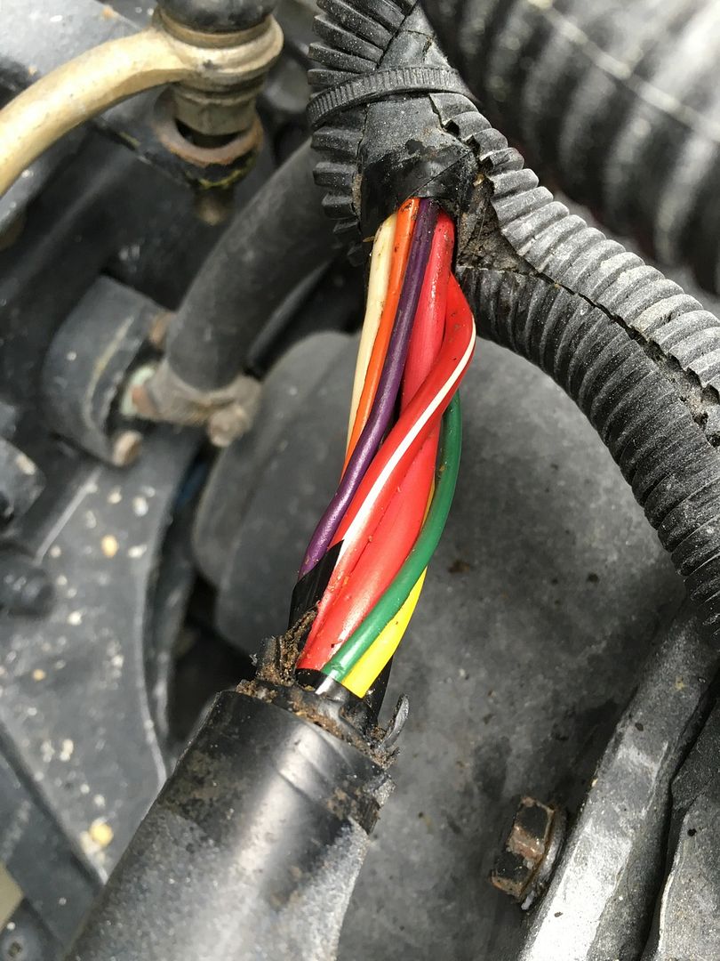
And here is a picture of the wiring bundle that is on the engine. You cant see all the wires but there is white, black, red, red with white stripe, green, orange, purple, brown, yellow.


And this is the same engine, this is the wire bundle after the big plug heading to the helm. All the same colors and with a meter I checked and made sure they all correspond or connect to each other. I have conductivity from the engine harness all the way to the end at the helm.

.

So this is what I am thinking about doing. The green wire to the water temp gauge, The red and red with white stripe together on one of these hooked up to the positive on the Volt gauge.


The black to the ground on the volt gauge. The orange to the oil pressure gauge. The purple just dead end cap it. The brown and the white come from the positive side of the coil so brown to tach gauge and white??. The yellow wire to the ignition switch. Try this on one engine and see what smokes.
 

alldodge

Moderator
Staff member
Joined
Mar 8, 2009
Messages
42,292
Black - agree
Yellow - agree, to start side of ignition switch
Purple - agree only , if you do not have an oil pressure light or warning buzzer, do not agree if you do have one of them
Brown - agree the tach
White - to run side of ignition switch

Your just talking the helm, so just to make sure the White needs to go to the positive side of the coil thru a resistance wire or ballast resistor for points distributer. Or white going straight to the Pos coil side for electronic
 

archbuilder

Vice Admiral
Joined
Sep 12, 2009
Messages
5,697
I'm thinking that if you hook the red and the red-white together you are going to create a short.
 

alldodge

Moderator
Staff member
Joined
Mar 8, 2009
Messages
42,292
Forgot about these
Green - agree
Red and Red White together - agree

Red is direct from BAT and Red/White is direct from the ALT. An amp meter is put between the two to show how much power is being pushed to the BAT or drained from.

New design runs direct from ALT to starter post (via 90 amp fuse) and main BAT pos cable is connected to same starter post
 

Mark72233

Ensign
Joined
Jul 11, 2014
Messages
926
AllDodge that sounds good to me.

Arch that is what concerns me also. I like the second diagram or picture. So what to do with these 2 10gauge wires. Red positive? Run it to the battery terminal on ignition switch? Than a jump wire over to the positive side of Volt gauge. Then what to do with the 10 gauge red wire with white stripe which is coming from the alternator. I know when I get this done hindsight it's going to seem so simple.
 

alldodge

Moderator
Staff member
Joined
Mar 8, 2009
Messages
42,292
You could either solder/crimp them together use a smaller gage wire to the volt meter
You could run the Red direct to the starter switch, cap the Red/White on the helm side, and cut the Red/White off the engine side and connect it direct to starter post
 

Mark72233

Ensign
Joined
Jul 11, 2014
Messages
926
AllDodge so you think the red white stripe wire can be capped and everything would function. And for the record what ever I end up doing if it smokes a wire or a gauge I am certainly not coming back on here and pointing a finger at anyone other than me for making the decision to have gone whatever route that may have been. :indecisiveness::tape::biggrin1:
 

alldodge

Moderator
Staff member
Joined
Mar 8, 2009
Messages
42,292
Yes it will work
Note, White wire is used like Purple in todays wiring.

New wiring does not use amp meters so they don't have to run heavy gage wires to/from the helm. Just cut the Red/Wht loose and attach to starter (orange)
Slide1.JPG


You could either run Red to switch (Orange) and remove and cap Red/Wht, or leave as-is and do as previously mentioned about connecting them together

Slide2.JPG


So far as not pointing a finger at me, I have no issue with that, this will work

Would also suggest putting a fuse inline in the Red feeding the starter switch of 20 amp, maybe 25 amp with old stuff and points not real sure on this point
 

Attachments

  • Slide2.JPG
    Slide2.JPG
    61.4 KB · Views: 0
Last edited:

Mark72233

Ensign
Joined
Jul 11, 2014
Messages
926
Oh if it works I will certainly point the finger back at you with a big thank you right behind it. Thanks I will give it a look tonight and figure something out.
 

alldodge

Moderator
Staff member
Joined
Mar 8, 2009
Messages
42,292
Just thought of something that may or may not have an impact.
Your original starter switches where heavier duty then your current ones. They should have been because more of the charging would need to go thru them and via the amp meter (new switches may not be able to take the full load). I have not looked at the ALT fully so I'm currently looking into the design to see if there would be an issue.
 
Top