72 Thunderbird Formula w/twin 165hp Mercs

Mark72233

Ensign
Joined
Jul 11, 2014
Messages
926
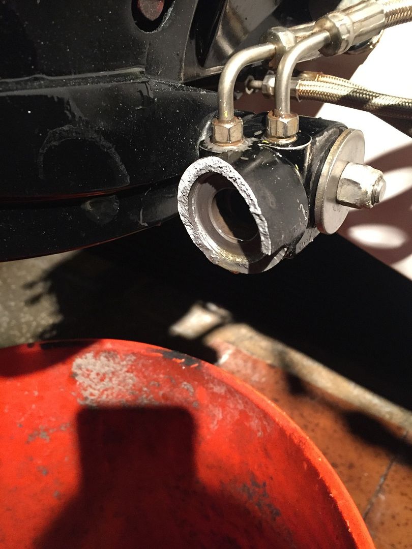
Thanks for the diagram AllDodge. That was the first thing I check and it was connected correctly it is the rams. Before I put them on I tested the 7 rams that I have and found the best 4 but when I say best I should have still taken them apart and rebuilt them. They are tight and sticking when I try to pull them in and out and after this one exploded I took it apart and it was nasty inside of it. Lessoned learned don't try and use rams unless they go in and out very smooth by hand.
 

Mark72233

Ensign
Joined
Jul 11, 2014
Messages
926
With some of my new parts I was able to get the second engine running and its running I think a little smoother than the first one. I put on the new manifold, water pump and starter. Rebuilt the fuel pump. Installed the new Pertronix ignition system and went to fire it up and yes I screwed this one up like I did the first engine, the distributor was 180* off. So set the engine back on TDC and pulled and rotated the distributor 180* which also meant that the valves aren't adjusted right so pulled the valve cover and readjusted the rockerarms and lets try that again and it fired right up. Adjusted the timing and both airfuel mixture screws on the carb and she is running sweet. I let it run in the driveway for about 30 minutes and no issues so I have 2 running engines waiting to be put into their new home. I also moved the boat out of the back yard where its been living for the past 14 months and back into the driveway so I can get it ready for the engines. I might try and get one in this weekend if the weather holds.
 

Challenger84

Petty Officer 1st Class
Joined
May 9, 2010
Messages
341
Wow! What a great read and one heck of a project. I read the entire 41 pages.. Can't wait to see the end results..
You're doing a terrific job! keep it up!
 

Mark72233

Ensign
Joined
Jul 11, 2014
Messages
926
Thanks for the kind words Challenger but you should have waited until closer to bed time, this would have bored you right to sleep 😜😴
 

archbuilder

Vice Admiral
Joined
Sep 12, 2009
Messages
5,697
Its nice to hear that 6 purrrr. Great job Mark, I'm jealous....I'm off doing other chores and you almost have your engine in!
 

Mark72233

Ensign
Joined
Jul 11, 2014
Messages
926
Thanks Arch, I cant wait to get them both in the boat and both running at the same time. I have run into an issue and need advise on. There is the small manifold for lack of a better term under the gimbal housing where the 4 trim ram hoses come from. There are the 2 nuts that hold the manifold in place that attach to the 2 studs that come down out of the housing. One of the studs has pulled loose from the housing. I tried JB Weld but it didn't hold so my next thought was a Thread Saver Helicoil or similar brand I just don't have any experience with this product. How do I figure out which one/size to purchase. The only info I can find on the stud is it is a .250-20/.250-28 x 1.380. I am guessing that it is 1.380" long. One end is 1/4" with 20 threads per inch(Course) which is the end threaded into the housing and the other end is 1/4 with 28 threads per inch (Fine).
 
Joined
Aug 17, 2009
Messages
941
Mark,

I just read your entire thread and you have put in some serious, serious effort. Everything looks fantastic. You should be very proud of yourself. The feeling of accomplishment will be amazing when you finish. Keep up the great work. We are all behind you and are anxiously waiting for the first splash. Carry on my friend.
 

Mark72233

Ensign
Joined
Jul 11, 2014
Messages
926
Thanks Greg, hopefully during the next couple of weekends I can make some serious progress getting these engines installed and the hull completely sanded. I still have to sand the starboard side, cap and bottom.
 

WOEISMEIGOTTA470

Petty Officer 1st Class
Joined
Aug 31, 2012
Messages
375
Thanks Arch, I cant wait to get them both in the boat and both running at the same time. I have run into an issue and need advise on. There is the small manifold for lack of a better term under the gimbal housing where the 4 trim ram hoses come from. There are the 2 nuts that hold the manifold in place that attach to the 2 studs that come down out of the housing. One of the studs has pulled loose from the housing. I tried JB Weld but it didn't hold so my next thought was a Thread Saver Helicoil or similar brand I just don't have any experience with this product. How do I figure out which one/size to purchase. The only info I can find on the stud is it is a .250-20/.250-28 x 1.380. I am guessing that it is 1.380" long. One end is 1/4" with 20 threads per inch(Course) which is the end threaded into the housing and the other end is 1/4 with 28 threads per inch (Fine).

Hi Mark,
Just make sure you know what thread pitch goes where. Measure the depth of the threaded hole to be repaired, then buy the correct length helicoil. Below is a link to the longest size I could find in 1/4-28,
.625"L

http://www.mcmaster.com/#91732a738

We use helicoils @ work all the time, to increase the strength of fastening aluminum plates together.
Progress looks good and that engine sounds real nice! Those pertronix kits make a hell of a difference eh?
 
Last edited:

Mark72233

Ensign
Joined
Jul 11, 2014
Messages
926
So far the Pertronix where easy to install and just a one time adjustment with the spacer provided. The coil seems to be a lot more intense than a stock coil as well. When I did a compression test I at first pulled the plug at the top of the coil and trails of lightning was coming out of the top like a Van de Graaff Generator so I had to pull the plug at the distributor. I will let you know in a year if they were worth the price. The compression test on both engines gave great results as well. The starboard engine compression numbers are #1-150psi, #2-150psi, #3-148psi, #4-146psi, #5-150psi and #6-148psi. The port engine had from 142psi up to 150psi so only minor differences between lowest and highest well within spec.
 

WOEISMEIGOTTA470

Petty Officer 1st Class
Joined
Aug 31, 2012
Messages
375
Those are good #'s. Mine tested about the same, all were within 5psi of each other at around 155psi. I can't wait to get mine running again now that it's in the boat. I just returned from a business trip to Toronto, anxious to start working on her again.
 

Mark72233

Ensign
Joined
Jul 11, 2014
Messages
926
Ok, I rebuilt my trim ram and double checked the hoses and the routes and pow, I blew up the same side ram.
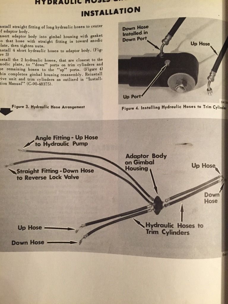
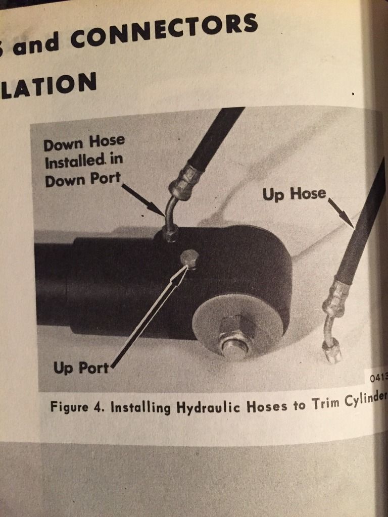
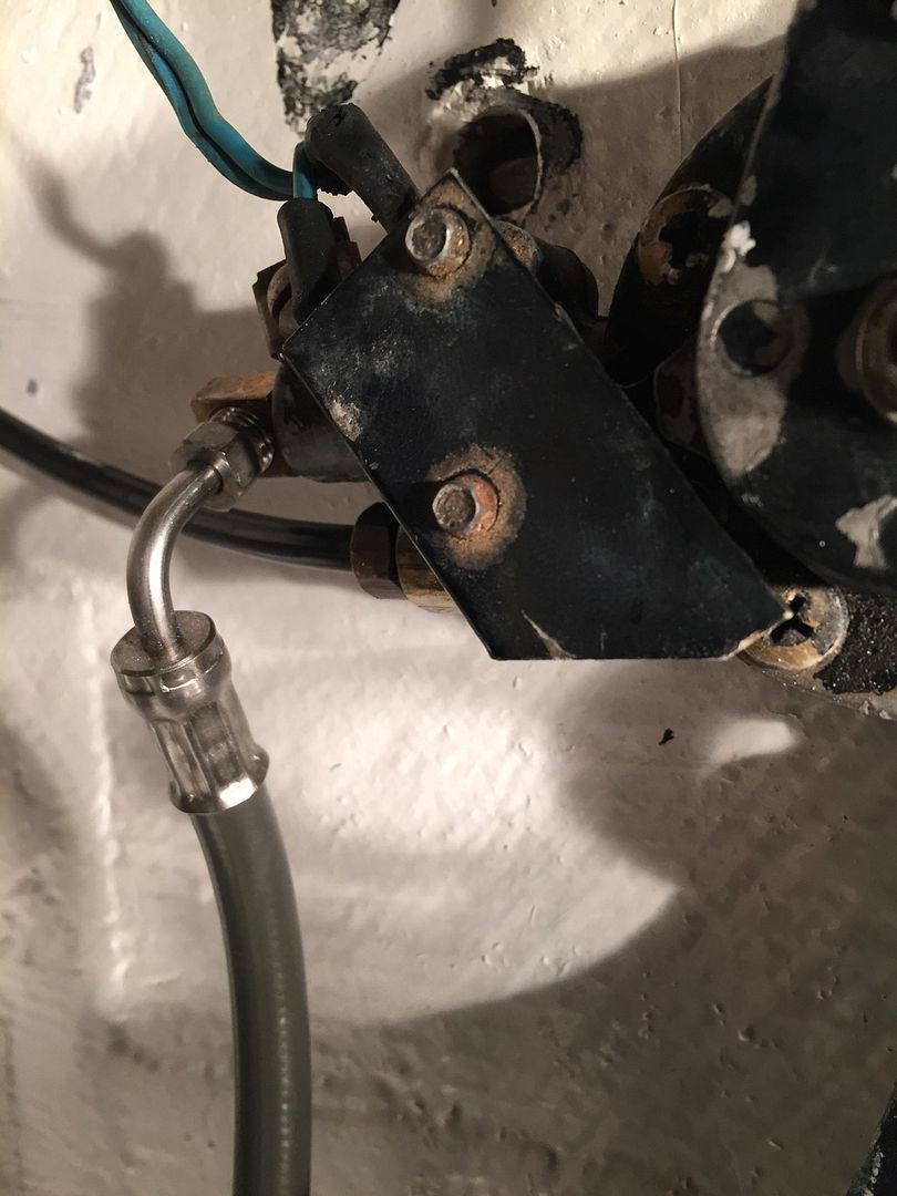
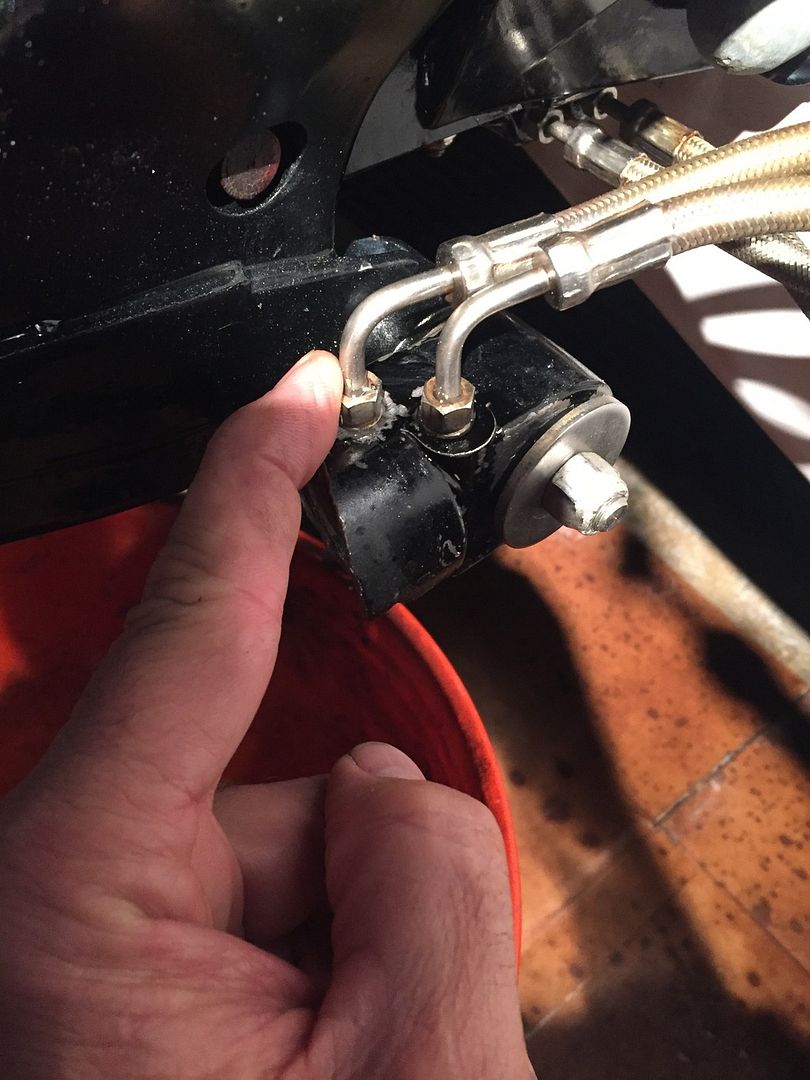
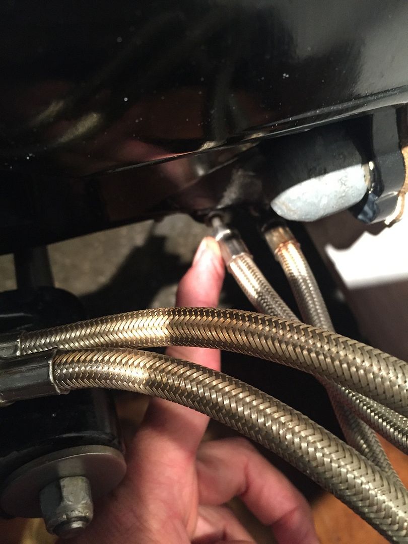
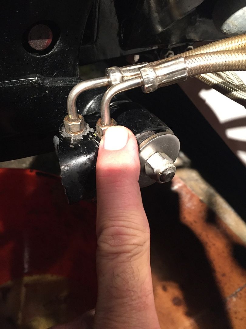
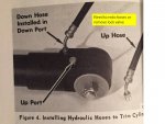
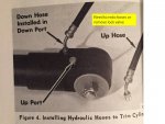
Now there is some confusing info about color of hoses so I double checked that and bought the black hoses and gray hoses and hooked them up where it shows to hook them up. In the above picture the black hose is the up line coming from the bottom of the pump down to the adapter body into the forward port. The gray hose is the down line and shows coming from the reverse lock down to the adapter body rear port. Going outside now under the gimbal housing to the hose adapter body where there are 2 outlets on both sides, forward outlets for up and rear outlets for down. As the below picture shows on the ram the forward ports should be hooked to the forward lines coming off the adapter body and the rear port furthest from the stern is hooked to the rear most hoses (down lines) coming from the adapter body.
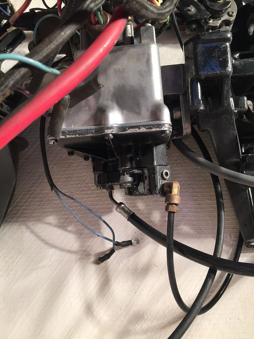
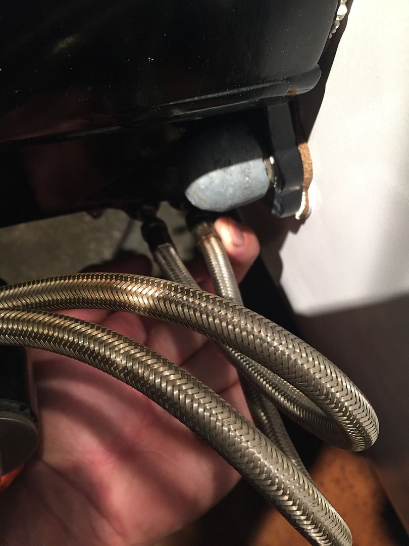
Here are pictures of my pump and hose and how they are hooked up. In the below picture is the black line (up) coming from under the pump down to the adapter body.
The next picture is the gray line (down) coming from the reverse lock to the adapter body. . The next four pictures are showing the lines attached to the rear of the ram running back to the adapter body.
 

Mark72233

Ensign
Joined
Jul 11, 2014
Messages
926
Some questions to anyone that knows. Is the black hose under the pump hooked to the right outlet on the valve body. Could I have a blocked return line letting pressure to build up. Why is it the starboard side ram on this engine that blows up and not the port side of this engine. The other engine is hooked up the same way but I quit running it afraid I will blow another ram, I am quickly running out of spare parts.
 

Mark72233

Ensign
Joined
Jul 11, 2014
Messages
926
I am starting to miss grinding fiberglass and wearing a hazmat suit during the summer at least I could finish something on move on to the next thing.
 

alldodge

Moderator
Staff member
Joined
Mar 8, 2009
Messages
42,079
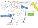
I think the problem is with doing the hose routing of a 1978 and later system with your system which is a 1972

Slide1.JPG


So if your going to hook it up using the 1978 and later setup, remove the valve IMO.


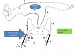
Slide2.JPG
Slide3.JPG

That said, I also think if your going to redo the hoses without the lock valve, you need different cylinders which have the fitting forward
 

Attachments

  • Slide3.JPG
    Slide3.JPG
    72.2 KB · Views: 0

Mark72233

Ensign
Joined
Jul 11, 2014
Messages
926
This is all the same system that was in place prior to doing the restoration. All the parts are the same and I have also purchased 2 more Rams of the same style so buying 4 more older style single line Rams is not in the budget right now
 

alldodge

Moderator
Staff member
Joined
Mar 8, 2009
Messages
42,079
Rams blow because the pressure exerted are exceeding the design. So either the pump is putting out more pressure then the rams are designed for (up in the down or the other way around), or the connections are wrong and again there is to much pressure. I cannot see what your seeing, but are you sure the installation is the same as it was prior to disassembly?
 
Top