1987 Evinrude 200hp outboard resto/rebuild

dehydrated

Petty Officer 1st Class
Joined
Dec 25, 2009
Messages
299
Re: Update 02-16-2011 Con'd

Re: Update 02-16-2011 Con'd

also when setting the crankshaft make sure the center main bearings align with the pins you will know when it does it kinda falls into place but make sure its seated right. gel seal less than 1/8th bead in the middle of deck .
 

j_k_bisson

Lieutenant Junior Grade
Joined
Oct 6, 2010
Messages
1,082
Re: Update 02-16-2011 Con'd

Re: Update 02-16-2011 Con'd

Just a question before I start assembling thing here reguarding these 1990 pistons and rings. My manual is a 1987, it does not cover the tapered ring and non tapered ring placement and direction. Which one goes on top, and which way does the taper go. I don't want to assume anything.

I noticed that there is a dowel pin to locate ring gap. Do I just assume that these only go one way. Ring placement goes by thickness of ring to slot and the taper direction is determined by dowel pin?
 

j_k_bisson

Lieutenant Junior Grade
Joined
Oct 6, 2010
Messages
1,082
Re: Update 02-16-2011 Con'd

Re: Update 02-16-2011 Con'd

1) Also wipe a small amount on center main bearing races to quieten engine down(this is a ficht mod).


Just to clairify you are talking about two middle main bearing where they slip on the locating pins in the journals.

2)Also do the upper bearing mod as it consists of replacing bolts with a tad longer and case hardened bolt to prevent breakage.(dealer item)

I did not get the new bolts. First time I heard about it. Do I really need them. It will put me on hold until next weekend. Is this really nessassary? It might have been done when the block was rebuilt the last time. Anyway to make sure?
 

Faztbullet

Supreme Mariner
Joined
Mar 2, 2008
Messages
15,671
Re: Update 02-16-2011 Con'd

Re: Update 02-16-2011 Con'd

Do I just assume that these only go one way.
yes...
Ring placement goes by thickness of ring to slot
Yes you could say so, if wrong ring is installed it will not recess into piston land nearly flush.Piston will tell ya if its in correct groove.
the taper direction is determined by dowel pin?
No as pin is there to keep rings from rotating...
Just to clairify you are talking about two middle main bearing where they slip on the locating pins in the journals
Correct.....
I did not get the new bolts. First time I heard about it. Do I really need them,Is this really nessassary?
Thats up to you as I update all engines I buiuld to latest spec's. You can build engine and come back and install them later. The new bolts are not S/S but either a anodized dark greenish black or gold color.
 

j_k_bisson

Lieutenant Junior Grade
Joined
Oct 6, 2010
Messages
1,082
Update 02-19-2011

Update 02-19-2011

Worked from 8 pm to 1:30am last night assembling the rotating assembly. Was quite happy with what I got done. Did not run into any problems and took my time and followed the book as I went. Wiped everything down again then relubed it as required in the manual as I went. Then double and triple checked eveything before they went together. Then double checked the torque on evey bolt twice. Did not make any stupid mistakes so far. Everything looks to be fairly tight (bearings) and the rod cap aligned perfectly. So we are good to go. Here are a few pics.

DSCN1457-1-1.jpg

DSCN1458-1-1.jpg

I stoped after I got the crank in and rod's torqued. I wiped the flages down and primed them. SO this afternoon I can start in on assembling the intake half of the block. Then some paint before supper I hope.

Anyone ever use the factor (BRP) paint before. I hope it drys fast. Like a couple of hours (3-4). That way I can star in on more assembling.:D
 

dehydrated

Petty Officer 1st Class
Joined
Dec 25, 2009
Messages
299
Re: Update 02-19-2011

Re: Update 02-19-2011

on the downhill slide now i forgot to send the petals ill put them in the mail asap . great feeling doing something yourself what else you have to do in the winter? oh yeah you did that
 

j_k_bisson

Lieutenant Junior Grade
Joined
Oct 6, 2010
Messages
1,082
Re: Update 02-19-2011

Re: Update 02-19-2011

Yep the boat is almost done, just the windshield and hand rail. The motor is well on its way. My wife will love when all this stuff is done. She'll get here budget back! LOL
 

j_k_bisson

Lieutenant Junior Grade
Joined
Oct 6, 2010
Messages
1,082
Update 02-19-2011 Afternoon

Update 02-19-2011 Afternoon

Just finished assembling the intake half of the crankcase. Then painting the whole block. The faces I did not want paint on I use grease and a paint brush to cover. Just have to wipe off the grease when the paint dries. Full steam ahead tonight. Hope to get all the external stuff assembled to the block. And go thru the reeds one more time.

Here are some pics so far.

DSCN1459-1-1.jpg

DSCN1460-1-1.jpg

The fun stuff starts now. I finally can have a beer or two. Haven't had a drink yet while the assembling was going on. I was a bit scared of screwing up the critical part.
 

j_k_bisson

Lieutenant Junior Grade
Joined
Oct 6, 2010
Messages
1,082
Update 02-20-2011

Update 02-20-2011

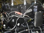
Was able to finish the fuel system side of the installation. Installed all new hoses for everything. There where so many air leaks in the old system it was unbelievable that this thing ran good at all. Also I used the proper zip ties for fuel lines that have the tabs on them. There is a difference. :eek: No air leaks! Still need to scrub my carb cover a bit more. Check out the pic. Looks like someone before me got some zinc primate primer on it. Right now its ok to keep the dust out of the carbs as it sits but I will clean it up before I'm done. Here some pics.

DSCN1461-1.jpg

DSCN1462-1.jpg

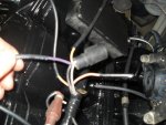
I ran into on piece of hose I can not figure out where two of the ends goes. Here is a pic.

DSCN1463-1.jpg

The large tubes goes to the bottom crank bearing relief fitting (left side) the other end (by the wrench) goes to the top relief fitting. The two that I can not figure out, is where the two small 1/8 lines hook up to. I can not find any nipples where they could possible hook up to. All the help anyone can give me would be great on this one. Pics would help as well. The manuals pics are black and white and do not show clearly where they go.

I also ran into another problem, I flipped the block up last night to install the thermostats and blackish oil (lubercating oil) dripped out of the exhaust port in the bottom of the block. This was all the extra lub oil I used to liberally oil things as I went through things. Hind sight now do not over do things with the oil) How do I ensure to drain this? Besides a complete tear down. I have not rotated the block since then and have let things drain out. But I want to make sure it does not cause a melt down.

Also do not need those reeds, when through them last night before installing them. There was not a single one that had an issue. So in they went.

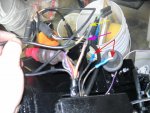
This afternoon and this afternoon I'll start into the electrical system cleaning and installation. I have a few questions for when I start installing.

1) To use die elcetric grease or not, on amphenol connectors?

2) Does some one have a wire rounting pics on their motor. I went through all my pics yesterday and I did not take any before I started removing the wiring. I thought I had. But I can not find them. This would be a greart help to locate the wire retaining straps in the proper spots. Right now I am trying to figure out where the shift interupter wire crosses over the top of the block. In front of the trigger or behind it. Also is there a retaining clamp up under there?

Thanks for all the help everyone that put their two sense in. It is very appreciated.
 

j_k_bisson

Lieutenant Junior Grade
Joined
Oct 6, 2010
Messages
1,082
Re: Update 02-20-2011

Re: Update 02-20-2011

Could the other two connections be for the cyd #5 recirc system? I only had 5 recirc hoses in the bag when I was making the new ones. I thought I lost one, so I made up a new extra one and put it on. I found a couple more pics but not of the area. (VRO pump hook up) It apears that the hose crosses over to the other side. So the only place I can think is the recirc # 5 cyd.

Any idea from anyone?
 

j_k_bisson

Lieutenant Junior Grade
Joined
Oct 6, 2010
Messages
1,082
Re: Update 02-20-2011

Re: Update 02-20-2011

Yep that hose went right where I though. So problem solved. Started going through the electrical system. Cleaning , testing and fixing where needed. This should be fun.
 

Faztbullet

Supreme Mariner
Joined
Mar 2, 2008
Messages
15,671
Re: Update 02-20-2011

Re: Update 02-20-2011

Right now I am trying to figure out where the shift interupter wire crosses over the top of the
block. In front of the trigger or behind it. Also is there a retaining clamp up under there?
It kinda lays in bottom of cowling and runs under #5 cylinder,behind coils on starboard bank to rear of powerpack.
 

wilde1j

Vice Admiral
Joined
Apr 15, 2002
Messages
5,964
Re: Update 02-20-2011

Re: Update 02-20-2011

Don't worry about any oil or grease inside, BC it won't be there seconds after you start it up and it clearly won't cause any harm before that.

A little grease on the electrical connectors is fine.
 

dehydrated

Petty Officer 1st Class
Joined
Dec 25, 2009
Messages
299
Re: Update 02-20-2011

Re: Update 02-20-2011

all wires run out the back side towards rectifier fron clip does nothing but hold the timer base will take pics tomorow of electrical and post them any specific shots you need?
 

j_k_bisson

Lieutenant Junior Grade
Joined
Oct 6, 2010
Messages
1,082
Re: Update 02-20-2011

Re: Update 02-20-2011

Shots of the starboard and port sides near the top. That is if it is not too much trouble. I need t figure out where the wire clamps go to hold down everything. Tonight I'm going to clean up the wire harness and try to install that. We'll see how that goes. Then its the timer base and power packs. Already got in the rectifier. So things are moving along quite nicely.

Thinking of removing the big connector in the wire harness and putting in a terminal strip like my Force had. I still have the universal harness in the boat and this would make it very easy for me to hook everything up. That is instead of patching in the Evinrude harness to the existing one in the boat. Just make a bracket and mount a univeral terminal strip for all the wire connections in the harness. I have so many cut wires already that this would make things more secure and clean. It's either that or a new wire harness that I really do not want to buy. We'll see.

Also I am cleaning all these plastic parts. They are clean but very whitish. Anyone have any suggestions on something to coat them. Like armour all or something? Just want them to look as nice as everything else.
 

dehydrated

Petty Officer 1st Class
Joined
Dec 25, 2009
Messages
299
Re: Update 02-20-2011

Re: Update 02-20-2011

napas got a product for black plastic for restoring but also spray paint for plastic can be found anywhere ill post pics tonight
 

j_k_bisson

Lieutenant Junior Grade
Joined
Oct 6, 2010
Messages
1,082
Re: Update 02-20-2011

Re: Update 02-20-2011

Well work last night going through the electrical system on a connector by connector at a time basis. Both cleaning the component, the connectors to that component, and the fastenting system. It is a long drawn out proceedure but I know from experiece it is well worth the time now. Better now than later when there is an issue. Like on the water.

Got the new stator installed last night and was a bit leary about how "CDI" wanted me to install the amphonel connectors to bullet connectors to snap into their units bullet connectors. I did it and soldered the bullet connectors together after getting everything crimped together. It just seams to me that a but connector soldered instead of bullet connectors is a way better way of doing things. The all covered with marine heat shrink. But hey I want to use the warrantly on the stator if I need to so we do it their way.

Also figured out how the interupter switch is routed last night after playing with it and reviewing the wiring diagram. Also got one of the power packs in. Could not find two of the bolts that hold the other one in. So I need to go out today and buy two more 1/4" SS bolts after work.

Started looking at that wiring harness last night. It is in rough shape. I think I will cut the wrapped electrical tape off it. H*ll, half of it is uncoiling/unravelling already. This way I can check for bad spots on the wires. Already found one on the two wires that send signal to the solinoid. Copper broke all the way through on one of them.

Order the new starter for this yesterday. I went with one of the aftermarkets from ebay. Anyone ever use one before? Do they have the power to turn these things properly? Or are they a bit under rated?

Still thinking about the terminal block idea instead of the big red connector. Anyone have any thoughts on this?

Here are some more pics for those of you who like to see them every day.

DSCN1470-1.jpg

DSCN1469-1.jpg
 

dehydrated

Petty Officer 1st Class
Joined
Dec 25, 2009
Messages
299
Re: Update 02-20-2011

Re: Update 02-20-2011

the port side powerpack has about a three inch bolt on the back side front side is same as the other side if that helps the clamps that hold wires one on top side by the timer base holds its wire you should find bolt boss there also another on starboard side to hold water lines going to water control valve.what did you think on the jetting for carbs? does your air box have baffles or not?(foamgasket like material inside the air box that would to me determine what jets are needed)
 

j_k_bisson

Lieutenant Junior Grade
Joined
Oct 6, 2010
Messages
1,082
Re: Update 02-20-2011

Re: Update 02-20-2011

the port side powerpack has about a three inch bolt on the back side front side is same as the other side if that helps the clamps that hold wires one on top side by the timer base holds its wire you should find bolt boss there also another on starboard side to hold water lines going to water control valve.what did you think on the jetting for carbs? does your air box have baffles or not?(foamgasket like material inside the air box that would to me determine what jets are needed)

Seeing that I do not have the water control valve sytem on this, do I still need the extra long bolt? A bit confused with the bolt (3")

The jetting I thought was ok (14, 50, 62) Is there something that needs to be corrrected? Not that fimilliar with this type of work.

Tha air box does have a baffle system in it. Also the foamgasket that mates up to the carb throats. How does this affect the jeting?
 

j_k_bisson

Lieutenant Junior Grade
Joined
Oct 6, 2010
Messages
1,082
Re: Update 02-20-2011

Re: Update 02-20-2011

Last night was able to mount the trim relay boax and the basic wire harness. Now it is time to figure out what all the cut wires are to. Need some help here from my freinds at Iboats. I'll post them in a different thread to get more response.

Here is how the evening turned out.

DSCN1477-1.jpg

DSCN1478-1.jpg

The new starter comes in today/tomorrow. So tat will help for some of the connections.

Last night I was trying to figure out if I do not mount the new trim sending unit for the guage in the mid section, will this affect the operation of the trim tilt system? Or is it just a sensor for position of the motor?

Also I had not planned on using the fuel pressure sensor, or the Vro pump. Using premix. What do I do with the plugs that are not connected. Fill them with ghot glue and tape them off? Or is there a cancel plug?
 

Attachments

  • DSCN1480-1.jpg
    DSCN1480-1.jpg
    125.5 KB · Views: 1
  • DSCN1471-1.jpg
    DSCN1471-1.jpg
    147.5 KB · Views: 1
  • DSCN1473-1.jpg
    DSCN1473-1.jpg
    141 KB · Views: 1
Top