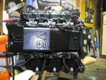
1987 Evinrude 200hp outboard resto/rebuild

nymack66

Petty Officer 1st Class
Joined
Aug 5, 2009
Messages
356
Re: Update 02-20-2011

Re: Update 02-20-2011

Hopefully this helps you, its for 88-89 it should be the same or very close...
1988_89_200_225.jpg
 

daselbee

Commander
Joined
Jan 20, 2009
Messages
2,765
Re: Update 02-20-2011

Re: Update 02-20-2011

Hmm...well...how do I start?....

Very nice post Andrew....but there will be significant differences. The 1987 has 2 powerpacks...the drawing shows the single pack used 1988 up. Alot of the other wires will be the same, but those for PP will differ. diodes, etc.

And, it just jumped out at me....look at the lower right corner wires. The wires from the powerpack to the coils. Using "creative licence" with the colors, they should all be orange solid or orange with a stripe. Look at the wire for #1. It is Blue with an indicated orange stripe. That is totally wrong. Should be orange with a blue stripe.

Just wondering what the source of this drawing is...did you download it, or scan it from Clymer or Seloc? If it comes from Clymer or Seloc, now it becomes clear that there are significant errors in those books....this wiring diag being one of them.
The rest of the diag is probably right, but that one wire just jumped out at me.

Just a point....
 

daselbee

Commander
Joined
Jan 20, 2009
Messages
2,765
Re: Update 02-20-2011

Re: Update 02-20-2011

Actually, looking again....the yellow pair from the stator to the terminal board....this drawing shows yellow and grey/ yellow. Wrong. It should be two yellows, one with a grey stripe.

Am I reading this diag wrong?
 

daselbee

Commander
Joined
Jan 20, 2009
Messages
2,765
Re: Update 02-20-2011

Re: Update 02-20-2011

WTF? I don't even see the reg/rect on here....those yellows should go to the reg/rect from the terminal board. To me it looks as if they are going into the powerpack.

Andrew, please post where you got this diag.
Thanks.

Edit....aw geez....look at the colors for the kill circuit....geez.
 
Last edited:

j_k_bisson

Lieutenant Junior Grade
Joined
Oct 6, 2010
Messages
1,082
Re: Update 02-20-2011

Re: Update 02-20-2011

Daselbee just for the record I have the 86-87 wiring diagram from the Factory service manual. I have been using it but it had left me with some questions. This pic does show the information that is not clear in my manual. So it is very helpful. I am not using it for colour just reference, just scmatically. It shows where some wires that are the same colour are actually wired together. Like the whitish/tan colour wire for the warning horn. That wire was the one that I had the most questions about. Thanks nymack66. It did help.

Only one question there though. This diagram show a diode in the system separating the fuel system to the heat system on the whitish wire. Does the 86/87 system have this same diode?
 

j_k_bisson

Lieutenant Junior Grade
Joined
Oct 6, 2010
Messages
1,082
Re: Update 02-20-2011

Re: Update 02-20-2011

Oh yes what does a diode do? And more specificly what does this diode do?
 

nymack66

Petty Officer 1st Class
Joined
Aug 5, 2009
Messages
356
Re: Update 02-20-2011

Re: Update 02-20-2011

Diode in any circuit is to allow current to flow in one direction ..In an Outboard this is what I found ....
The purpose of the diode is to prevent the electrical path of the vacuume switch circuit from reaching the "I" terminal of the ignition switch, which would by-pass the key switch. If the diode fails in a closed condition while the engine is running, the vacuume switch would then supply current to the ignition even with the key switch off. If the diode fails in the open condition, it would go unnoticed when starting, because the vacuume switch closes readily, energizing the shift circuit.
To check diode separate diode connector to cable assembly. Connect one ohm-meter (hi ohms scale) lead to ignition terminal on key switch and other test lead to diode connector. A normal diode will show a reading in one direction and no reading in the other direction. A test light should show with connections in one direction only.
 

daselbee

Commander
Joined
Jan 20, 2009
Messages
2,765
Re: Update 02-20-2011

Re: Update 02-20-2011

Daselbee just for the record I have the 86-87 wiring diagram from the Factory service manual.
..... Thanks nymack66. It did help.

Only one question there though. This diagram show a diode in the system separating the fuel system to the heat system on the whitish wire. Does the 86/87 system have this same diode?

Yes, nymacks post absolutely was good info.....but I still want to know where he got it.

So you are good to go with the proper wiring diagram. A diode is a semiconductor that allows current to flow only one way. When forward biased, current will flow thru it as it is designed in the circuit. When reverse biased, no current flow.

There are two leads on a diode, the anode and the cathode. When the anode is positive with respect to the cathode...i.e. when the anode is at +12v and the cathode is at ground, current will flow. Reverse the polarity, and it is reverse biased, and no current flow.

In almost every case on an outboard, the diodes placed here and there in the harness are blocking diodes. They serve to isolate one circuit from another UNLESS (by design of circuit) one of them goes positive with respect to the other. Then the diode allows current flow...and this is all by design of the circuit as specified by the engineers.

A significant difference is the diode bridge within the reg/rectifier. That has a different purpose....but still functions exactly the same...lets current flow only when the polarity is "right".
 

daselbee

Commander
Joined
Jan 20, 2009
Messages
2,765
Re: Update 02-20-2011

Re: Update 02-20-2011

The purpose of the diode is to prevent the electrical path of the vacuume switch circuit from reaching the "I" terminal of the ignition switch, which would by-pass the key switch. If the diode fails in a closed condition while the engine is running, the vacuume switch would then supply current to the ignition even with the key switch off. If the diode fails in the open condition, it would go unnoticed when starting, because the vacuume switch closes readily, energizing the shift circuit.

Respectfully, Huh? I don't get this. All +12 v is sourced/supplied thru the ignition switch. The vacuum switch merely shunts a tan wire to ground if the vacuum is too high on incoming fuel line.


Where did that diag come from? I would like to know.
 

j_k_bisson

Lieutenant Junior Grade
Joined
Oct 6, 2010
Messages
1,082
Re: Update 02-20-2011

Re: Update 02-20-2011

So where is the diode in my harness? And what does it look like.

Tonight I cut off all the old electrical tape and removed all the unused wires. Ie the vacuum switch, the VRO pump connection, the oil tank connection. Did not see any thing that looked like a inline fuse molded into the harness.

I did not touch any of the red wires as my diagram shows the diode is located on.

Only touched the tan wire that went to the vacuum switch, the purple wire that came from the VRO pump, and the three wires that came from the VRO oil tank and pump. Nothing red. Also I only shortened them.

I also went through all the connections testing OHMs throught the main plug to contact points, and the only one that is troubling me is the ground. When I check the gray wire coming from the rectifier to ground I get a resistance there. Should it be there. I realize that the gray wire is the tach wire. But sould it have a resistance?
 

boobie

Supreme Mariner
Joined
Nov 5, 2009
Messages
20,826
Re: Update 02-20-2011

Re: Update 02-20-2011

I'm confused. You are talking about vacuum switches and diodes on this mtr. Where are they??? Unless you're going back to 1968 or so the only vacuum switch I know of on the newer mtrs is the fuel restriction switch used on V-6's. The diode on these newer mtrs is in the wiring harness to keep false signals from putting the mtr into SLOW. It's in the tan wiring circuit of the mtr. Please enlighten me.
 

daselbee

Commander
Joined
Jan 20, 2009
Messages
2,765
Re: Update 02-20-2011

Re: Update 02-20-2011

Jeff...just don't worry about any diodes. They may or may not be on your motor like Boobie says. I still haven't seen the diagram for YOUR motor, so I cannot say. IF they are there, they will be embedded in the harness, all wrapped up. Very difficult to find. And, in my opinion, not an item that fails very often. I wouldn't worry about a blocking diode (if it exists), until you have to.

I have never measured the grey to ground, but for sure, it would not surprise me to read some resistance when measured like that.
I wouldn't think a thing about it.

Keep up what you are doing. Looks very very good so far.
I am going to sit back and follow this silently.

Edit: Yes Boobie, I just looked this motor up, and there is a vacuum switch mounted right next to the fuel pump. Maybe a diode in the harness...not sure.
 
Last edited:

jonesg

Admiral
Joined
Feb 22, 2008
Messages
7,198
Re: Update 02-20-2011

Re: Update 02-20-2011

So where is the diode in my harness? And what does it look like.

I have a note scribbled on the circuit diagram in my manual.
"Diode is close to the cannon plug."
It would feel like a bump in the wiring but you would need to unwrap the harness to feel it.
 

nymack66

Petty Officer 1st Class
Joined
Aug 5, 2009
Messages
356
Re: Update 02-20-2011

Re: Update 02-20-2011

Jim
Use a 12v DC source and a light bulb then test by applying voltage to each wire whilst the harness is out and not connected to the engine to check for the presence of Diode you do NOT have to assume if its there or not. You will want to apply this current flow not from the red plug but from the ends of each wire. You will also be verifying if the harness has any fault since you are re-using the old one.
Doug the diagram I posted is from the Cylmer manual.
 

j_k_bisson

Lieutenant Junior Grade
Joined
Oct 6, 2010
Messages
1,082
Re: Update 02-20-2011

Re: Update 02-20-2011

Like I said I cut off all the electrical tape last night from the harness, it was coming off anyways and needed to be fixed. I did not notice any bumps like a molded in fuse link. I can tell you where the tan wires all come together, about 3" above trim relay box, they are all soldered, crimped, and shrinked wraped together. I just cut the extra wires there about 3/4" from this "connection" and then marine heat shrinked them, sqeezing them to make seal when hot. So what ever diode is there is still there. My concern with this diode was if it was in one of the connectors where the shift interupt switch and the power pack are. Just wanted to make sure that there was not some kind of order that these connection here and that bull crap. Because all three connectors could go to any one of each other on these tan wires up under there.

Well I finished off the electrical last night other than mounting my new starter. It hadn't come in until this morning. So it gets mouted tonight. Here is how the electrical came out. Everything nice and cleaned up. I'm sticking with the factory plug. Not going with the terminal block. I'll just patch the harness from the boat to the harness from the engine in the boat after hatch. That'll be fun!:facepalm:
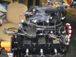
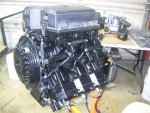
DSCN1486-1.jpg

DSCN1493-1.jpg

DSCN1494-1.jpg

Also to finish out my questions on the additional idle rework curcuit that Faztbullet directed me to do. Here is how the end of the hose at the top of the block and how it terminated. Is this correct? Will this discharge oil spray like a disconnected PVC valve on a car engine? Should I make up a foam breathable cover of the end. It will help with reducing the oil mist issue. Just do not want a fire in the stator. Here is the pic of how it terminates now with out foam cover.
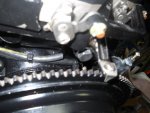
DSCN1488-1.jpg

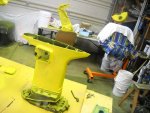
Tonight I am taking off work and getting out of the garage. lol This weekend I move on to the mid section. Here is how it sits. All prepped and ready for paint.
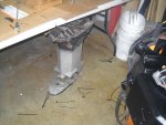
DSCN1497-1.jpg

I figure that I will paint everything in the midsection and transom plates. I love my gas mask! :D Then give them a couple of days to dry properly before assembling things. Al the while I am rebuilding/resealing the trim unit. Still waiting on my special wrench from Austraila to come in so I can remove the cylinder caps. It was way cheaper than buying it in North Amercia even with shipping.

Also need to severly clean up the garage again. Wow are the zip tie pieces all over the floor are starting to get thick!

My only worry about this whole rebuild is my top two carbs. When I was torquing down the four car bolts on the top two carbs. The factory service manual stated that the bolts should be torqued to a very high torque for a plastic carb in my opintion. It sort of warped them a bit when I was torquing, so I stopped well before I fully torqued them. I might remove them and check them for air leaks in the bowls. It appears it might of warped the flat plan the bowls seal on. Anyone else have this problem with the book on this one torque. I just tightened the rest by hand and feel. But I might need to buy a couple of carbs to replace them if there is a leak. Damn! Don't know yet.

If anyone can anything else I might have problems with please let me know.
 

daselbee

Commander
Joined
Jan 20, 2009
Messages
2,765
Re: Update 02-20-2011

Re: Update 02-20-2011

Thanks Andrew. I too use the Clymer for some certain specific questions. Mostly I ignore it though. I was looking at the Clymer for my '96, and found another wire color error just last night.
I am hoping that all reading this will realize that the best proper manual is the factory service manual, and it is this specific level of errors in the Clymers and Selocs that drive home the point.
 

nymack66

Petty Officer 1st Class
Joined
Aug 5, 2009
Messages
356
Re: Update 02-20-2011

Re: Update 02-20-2011

Excellent work Jeff, I am in the process of hand sanding my Cowling on my restoration. Fun stuff as you know ...Hey at lease I am Green !!

DSCF0010-2.jpg
 

j_k_bisson

Lieutenant Junior Grade
Joined
Oct 6, 2010
Messages
1,082
Update 02-25-2011

Update 02-25-2011

That green primer sure looks good! I hope the green stuff you are using is high build as it looks it. Because this "Tempo Yellow Zinc Chromate Primer" crap is not high build at all. Its as thin as paint thinner with a drop of paint in it. Here are a couple of pic of the parts after four completely empty cans.

DSCN1500-1.jpg

DSCN1501-1.jpg

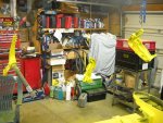
I you look into the back ground of the one pic you will see Big Bird and Elmo keeping my motor nice and clean. Got to keep the kids from seeing the old sheet. They'll want it for the bed again, reguardless of the rips in it. LOL

Anyone know if this Tempo primer is ready for paint, no sand, or does it needs to be sanded? I was planning on taking a scotch brite to it before I painted. Just want to know for sure.

Tonight everything gets painted Evinrude Silver-blue. The correct colour for 1986-87.

Talking with an ebay graphic supplier about them remaking the factory grahics. Still waiting on a cost for that.

Hey anyone have a 5" extension kit for this motor they want to sell?
 

j_k_bisson

Lieutenant Junior Grade
Joined
Oct 6, 2010
Messages
1,082
Re: Update 02-25-2011

Re: Update 02-25-2011

Oh yes I learn't another lesson yesterday. I brought in my one motor mount to work to have that seized bolt burnt out by the EMD deptment. Did anyone know that EDM fluid eats rubber engine mounts for lunch. So I am now on the look out for a pair of lower engine mounts for this motor. Just when I thought I have the majority of parts purchased.

My luck showing through again........
 

daselbee

Commander
Joined
Jan 20, 2009
Messages
2,765
Re: Update 02-25-2011

Re: Update 02-25-2011

Just so hasppens I have some good mounts.
 
Top