1981 Bayliner Victoria 2750 - Restore or Bust

GWPSR

Senior Chief Petty Officer
Joined
Jul 25, 2012
Messages
758
While grilling the sausages for dinner last night, I sanded the edges of the anchor rope locker smooth, and overdrilled the hole for the pop-up handle:

20140623_194007.jpg


then masked it off and filled it with thick resin and cabosil. I'll redrill the 1/4" hole for the handle in the center when cured.
 

Tboner7864

Petty Officer 2nd Class
Joined
Mar 27, 2013
Messages
177
Hey GWPSR been a while since I posted all I can say is WOW I may not even get to work on mine this year but. But that is Okay. I have to work on our house first:). I got my little 14' bayliner workin so were still boatin. Cant wait to see you splash that baby definitely keep it coming I will be using your restore as my holy bible on the day I get to play with Blue Grandma
 

Tboner7864

Petty Officer 2nd Class
Joined
Mar 27, 2013
Messages
177
Hey GWPSR been a while since I posted all I can say is WOW I may not even get to work on mine this year but. But that is Okay. I have to work on our house first:). I got my little 14' bayliner workin so were still boatin. Cant wait to see you splash that baby definitely keep it coming I will be using your restore as my holy bible on the day I get to play with Blue Grandma.
 

GWPSR

Senior Chief Petty Officer
Joined
Jul 25, 2012
Messages
758
Good to see you TBone. Yeah, slowly but surely we're picking away at the tasks.

Over the weekend for example, I created a template out of 3/8" plywood, clamped it to the bottom side of the engine hatch, and used the router to remove a rectangular section of the hatch core while leaving the 1/4" thick skin. This was necessary in order to properly repair a 4" diameter hole the PO had cut in the hatch to attach a fighting chair, and a 1.5" diameter hole they cut to install a pull ring.

The pull ring never needed to be cut all the way through, just recessed a little. The 4" hole, which had been directly over the carburetor/spark-arrestor was the reason the original motor filled up with water.

After removing the plywood core (rectangular with rounded corners) -- sorry, no pics, it was miserable outside this weekend, mid-90's with extreme humidity -- I ground the back of the skin to solid glass.

I prepared a piece of new 3/8" plywood to fit the void, and laminated 3 layers of 17 oz biax and one layer of 10 cloth to one side. That resulted in a 1/2" thick plug.

Covered the holes on the outside with masking tape, and filled from the back side with thickened resin (epoxy and cabosil) and then buttered the fiberglassed side of the insert and pressed it into place. Filled the minor void between the existing core and insert with PB and smoothed.

I will later grind the gelcoat on the bottom side surrounding the patch, and lay a piece of 10 oz cloth over the bare plywood. There was no glass on the bottom side of this hatch, just gel over bare plywood originally.

On the outside, I will use the die grinder to recess the area for the pull ring, and will also take the area of the 4" hole just slightly below the surface and feather it our to the surrounding area, and lay some cloth in and fair over it.
 

GWPSR

Senior Chief Petty Officer
Joined
Jul 25, 2012
Messages
758
Filled holes as seen from top:

20140630_181630.jpg


From the back (haven't ground and glassed over yet:

20140630_181740.jpg


And the pull ring and 4" hole after a session with the die grinder and orbital sander:

20140630_184741.jpg
 

Tboner7864

Petty Officer 2nd Class
Joined
Mar 27, 2013
Messages
177
The PO must have liked Swiss cheese ;) luckily I don't have many holes in my hull only the ones that the manufacturer put there
 

GWPSR

Senior Chief Petty Officer
Joined
Jul 25, 2012
Messages
758
The back side of the core patch, ground and feathered:

20140701_170943.jpg


And after a layer of 10 oz cloth:

20140701_174044.jpg


Later yesterday evening, gwpjr laid the final piece of 6 oz cloth on the sole over the fuel tank:

20140701_195405.jpg


When it's 90° outside, it's over 100° under the tarp (yes, that's why all the pics are tinted green) in the boat. At least tonight the humidity was down to 40% instead of the 70%+ it's been the last few days.
 

GWPSR

Senior Chief Petty Officer
Joined
Jul 25, 2012
Messages
758
Yesterday I spent an hour or two measuring and making drawings, then cardboard templates for the two sections of firewall that become tabbed to the hull and sole, and fitting/trimming them for approximate fit. Afterward, the templates were transferred to 1/2" BC plywood. I spent probably another hour scribing and trimming til they fit just how I wanted them to.

A little later in the afternoon. I installed both and filleted and tabbed them on both sides with 17 oz biax:

20140702_190946.jpg


20140702_190937.jpg


Maybe I'll get ambitious and start planning the motor mounts today.
 

GWPSR

Senior Chief Petty Officer
Joined
Jul 25, 2012
Messages
758
Today I drilled pilot holes through the transom, using the largest bit that would fit into the small chuck on my drill guide. I C-clamped the guide base to the transom to ensure that the hole was perpendicular to the outside skin, and that the bit didn't wander.

20140703_140009.jpg


20140703_140001.jpg


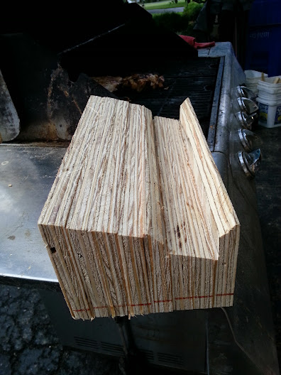
Later I began to prepare for the motor mounts. I ripped lengths of 3/4" plywood with a 15° bevel on one edge (matching the deadrise angle) and made 16 pieces 1 foot long each:

20140703_161833.jpg


Each motor mount is 12" long by 6" wide. The height above the sole is about 4 1/2" on the outboard edge and 5 1/2" on the keel-side edge. A few test fittings and trimming and we have the basic shape established:

20140703_190009.jpg


This is upside down as it appears. The large kerf is where the small stringer runs through the bottom of the mount.

There is plenty more work to do on them. They need to be rounded over on all exposed corners. I'm planning to add a mortise just over halfway through horizontally from the side so I can use bolts, washers and nuts rather than lags when I mount the engine. The outer edges of that mortise will also be rounded over so that I can more easily glass inside the mortise. I'll also soak the finished assembly in resin before I glass it.
 

GWPSR

Senior Chief Petty Officer
Joined
Jul 25, 2012
Messages
758
Happy 4th of July! :usa2:

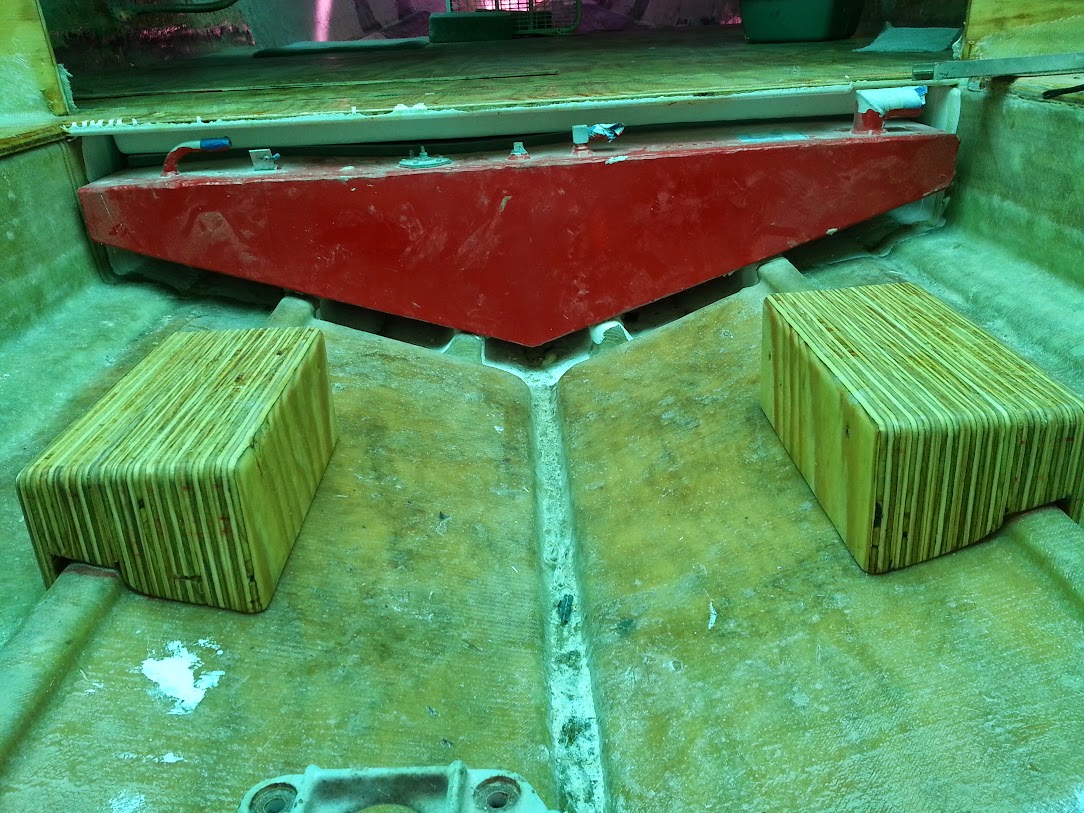
In celebration, I glued up all the layers of the motor mount blocks, sanded all sides fair and rounded the exposed edges on the router table:

20140704_143500.jpg


20140704_143522.jpg


20140704_145712.jpg


And gave them as much thinned epoxy as they would drink:

10533466_10152287072803925_300171876_n%255B1%255D.jpg
 

Mikeopsycho

Senior Chief Petty Officer
Joined
Feb 6, 2014
Messages
738
Wow, nice motor mounts! She's really coming together. Keep up the great work! :clap2:
 

GWPSR

Senior Chief Petty Officer
Joined
Jul 25, 2012
Messages
758
Saturday's fun included dry-fitting the completed motor mount blocks:

20140705_134325.jpg


10508251_10152289405723925_2038177534_n%255B1%255D.jpg


then gluing therm down and filleting them with PB. While the PB was still soft, I began tabbing them in. I started with 3" wide strips of 17 oz biax diagonally out from each corner onto the hull, and up the corner and over onto the top. Then came 6" wide strips along all four sides, wrapped around the corners as well. Finally another layer of 17 oz laid over the top and down onto each side and onto the hull to encapsulate the whole mess.

20140705_164343.jpg


10533618_10152289785788925_1532311512_n%255B1%255D.jpg


The cloth molded pretty nicely around the corners. There will be a minimal amount of sanding required to remove stray fibers sticking out, and little or no fairing needed.
 

GWPSR

Senior Chief Petty Officer
Joined
Jul 25, 2012
Messages
758
Today I sanded the mount blocks and then laid 17 oz biax over the shelves in the engine bay:

20140706_161158.jpg


I think I'm finally done on this end of the boat!
 

bigdirty

Senior Chief Petty Officer
Joined
Oct 4, 2013
Messages
652
Lookin good man! :thumb: Got a motor to toss in there yet? After a run in mine, i'd personally never go back to a single small block V8 in a boat this size.. will the volvo drive you have hold up to a big block? Just throwing my $.02 in, as my old chriscraft was about the same size and with a 350 she was a bit of a slug.. and its not all about flat out speed, but more so having the power in rough chop to keep moving forward, and possibly get back in bad weather if you get caught in something... Either way, its looking awesome, keep up the great work!
 
Last edited:
Top