My boat is being a boat . . .

tpenfield

Moderator
Staff member
Joined
Jul 18, 2011
Messages
18,085
Does your PIR have any adjustment? Maybe you could dial down the sensitivity..
The only adjustment is the shut-off delay.

I've come up with an alternative, which will be an indicator light for the light switch. So, if someone does go to the head and does not know how to turn on the light, it will be fairly obvious.
 

tpenfield

Moderator
Staff member
Joined
Jul 18, 2011
Messages
18,085
OK, for my next trick, I am going to add some position indicators for the trim tabs and convert the outdrive trim indicators to an electro-mechanical set-up where the pricey trim senders do not have to live in the water.

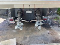
Trim Tabs - My boat really needs the trim tabs to come up on plane, and they are fairly large (12" x 18"). Last year I did not use them much, because there are no position indicators. I know I can get the tabs with the electronic indicators, but my experience is that the electronic senders that are under water last a few years and then you are replacing them. Mechanical senders are God-awful expensive, geared more towards the GFBL boat crowd and would be hard to install the display up at the helm. So, I've cobbled together some bits and pieces to use control cables under water and an electronic gauge up at the helm. We shall see how that goes :unsure:

Outdrive Trim - The senders that go on the outdrive are $150 each (3-wire digital type). The starboard sender was bad when I bought the boat and I just connected one in the engine compartment last year, so the SmartCraft system would not get upset and shoot out yet another warning. My plan is to use a control cable thingy to mimic the position of the trim rams and bring that up inside the engine bay to actually 'turn' the senders rather than having the outdrives do it directly.

I have saved the cables that I used on my previous boat where I made a similar setup using a 200mm slide potentiometer. This setup should not be quite as involved as I am using the Mercruiser trim senders, just modifying how they are mechanically operated. The trim position already shows up on the VesselView display along with other critical aspects of the engine/vessel.

Based on my luck so far, these modifications should be another mission impossible.
 

tpenfield

Moderator
Staff member
Joined
Jul 18, 2011
Messages
18,085
Quick Update . . .

I fixed the plumbing . . . the new section of red supply line that I installed was a wee bit short, causing the whole mess not to go together properly. Now all set, no leaks. :)
 

tpenfield

Moderator
Staff member
Joined
Jul 18, 2011
Messages
18,085
Having better luck with mechanical stuff today . . .

I got the control cables installed for the tabs and outdrives.
.
IMG_4663.jpg
.
Having drilled a few holes in this boat, I got to say that the fiberglass is really thick. . . almost too thick. I bet the boat would be just as solid with a little less fiberglass and weigh about 1,000 lbs. less. :rolleyes:
 

tpenfield

Moderator
Staff member
Joined
Jul 18, 2011
Messages
18,085
Of course, now that I'm hooking up position indicators, the port Trim Tab is frozen and move does not want to . . . why wouldn't it be frozen :rolleyes: I put a few hundred pounds of lifting force on it to get it to contract some, but it only moves part way.

The starboard side works fine.

I know that Tabman is no longer with us . . . wondering if there are other trim tab Guru's on the forum. :unsure: They are the plain basic Bennett tabs from the looks of them.
 

flashback

Captain
Joined
Jun 28, 2002
Messages
3,976
I no nothing! But will say that the ram on the port side looks a bit rusty. But I do have a couple of non related questions..
What is the rectangle thingy in the center of the transom? Maybe a mount for a pusher..? And will the remote cables freeze up from corrosion?
 

tpenfield

Moderator
Staff member
Joined
Jul 18, 2011
Messages
18,085
After a little more effort trying to figure things out . . .
OMG !!! The switches are hooked up reversed !!! o_O

The trim tabs both actually work, but the starboard switch runs the port tab and vice versa . . . :rolleyes:

I got to swap out some wiring.

This had to be that way since the boat was new . . . either that or they got replaced along the way and the service tech wired them up wrong. :unsure:
:rolleyes:
 

Scott Danforth

Grumpy Vintage Moderator still playing with boats
Staff member
Joined
Jul 23, 2011
Messages
49,854
Ted. It's wired correctly

The port side switch is supposed to operate the starboard side and visa versa

If you want port side bow down, you press port side switch forward and the starboard side extends, lowering the starboard tab, which lifts the starboard arse and drops the port side bow
 

tpenfield

Moderator
Staff member
Joined
Jul 18, 2011
Messages
18,085
Ted. It's wired correctly

The port side switch is supposed to operate the starboard side and visa versa

If you want port side bow down, you press port side switch forward and the starboard side extends, lowering the starboard tab, which lifts the starboard arse and drops the port side bow
I get it, but it seems weird to be . . . I usually think of which side of the boat needs to go up :LOL:

I switched the hoses at the pump, which was pretty simple.

With the tabs all sorted out, I was able to test out my homemade senders.
.
The ram travel is only about 2.5 inches, so I was able to use the standard C33 cables. They need a little bit of adjustment.

View attachment tt-sender1.mov
 

tpenfield

Moderator
Staff member
Joined
Jul 18, 2011
Messages
18,085
Why not just install Tab indicators, no need for the auto stuff
https://bennetttrimtabs.com/product/electronic-indicator-control-kit/
I thought about it, but preferred not to put any electronic stuff below the water line. I did not have the helm space for the mechanical indicator display, else I would have run a 100% mechanical system, like I had on my F-242. So, this was a compromise.

This year, I am going to try using more trim tab to help the boat get on plane. In doing so, I'd really like to know the position of the tabs.
 

Scott Danforth

Grumpy Vintage Moderator still playing with boats
Staff member
Joined
Jul 23, 2011
Messages
49,854
Ted, I would suggest a longer tab for more surface area if you have a problem with the hole shot
 

tpenfield

Moderator
Staff member
Joined
Jul 18, 2011
Messages
18,085
BTW - in looking at the digital trim senders for the outdrives, I noticed that they are on the port side of the gimbal ring, where the old-school analog senders were on the starboard side.

Not sure why Mercury changed it, but it is a good thing I noticed.
 

tpenfield

Moderator
Staff member
Joined
Jul 18, 2011
Messages
18,085
Ted, I would suggest a longer tab for more surface area if you have a problem with the hole shot
Yes, that would be a next step, if the use of the existing tabs does not work out. These are nearly the biggest tabs that are readily available. 18" wide x 12" deep. The transom mounting surface only supports up to 18" width, so to go bigger, I'd be looking at an 18" x 15" or possibly an 18" x 18". I believe I'd need something a bit custom with 2 tab cylinders for each trim tab.

One of my concerns when I was originally looking at this boat (vs. the others that I considered) was that the running length of the hull is about 18" shorter than similar boats (Formula 330 CBR, Chappy 327). The transom on the CY 328/338 is recessed quite far under the integrated swim platform. So, it has the LOA and weight of a 33 foot boat, but the hull is kind of like a 31 foot boat.

I think Cruisers knew this about the design, thus the large trim tabs.
 

alldodge

Moderator
Staff member
Joined
Mar 8, 2009
Messages
42,308
I thought about it, but preferred not to put any electronic stuff below the water line. I did not have the helm space for the mechanical indicator display, else I would have run a 100% mechanical system, like I had on my F-242. So, this was a compromise.

This year, I am going to try using more trim tab to help the boat get on plane. In doing so, I'd really like to know the position of the tabs.
Don't understand but ok
The coil is fully enclosed inside the cylinder and covered in hydraulic oil. The original top cap is removed and replaced with new cap (sealed same as before)
 

Scott Danforth

Grumpy Vintage Moderator still playing with boats
Staff member
Joined
Jul 23, 2011
Messages
49,854
I would go 15 long. You will need to form it like the sport tabs for support, however a single ram will work

Agree with AD, the sensors sit in the cylinders
 

tpenfield

Moderator
Staff member
Joined
Jul 18, 2011
Messages
18,085
Thanks guys ! Yes, on the Bennett tabs, they are probably the better design for underwater sensing. If I have to replace the tabs/cylinders in the future, I'd probably go with the electronic indicator type.

As for the size of the trim tabs, If I need to go to a 15" depth, I am thinking I'd get a whole new system with built-in indicators. Bennett has some 'premier line' of tabs, but I probably need to start saving my weekly allowance ($$$)

My greater concern are the outdrive indicators, since if you look at them the wrong way, they go bad :LOL:
 

Scott Danforth

Grumpy Vintage Moderator still playing with boats
Staff member
Joined
Jul 23, 2011
Messages
49,854
I would send a file to the laser and bribe the brake press operator with a 12 pack...... LOL
 

tpenfield

Moderator
Staff member
Joined
Jul 18, 2011
Messages
18,085
I would send a file to the laser and bribe the brake press operator with a 12 pack...... LOL
If need be, I was thinking about getting 21" x 15" pieces of stainless steel. Bend an inch of the edges up to a right angle for stiffness and just fasten the whole thing (now 19"x15") to the underside of the existing tabs. :unsure:

Also thought about making some transom pods, but not sure I want to go that distance. :LOL:
 

tpenfield

Moderator
Staff member
Joined
Jul 18, 2011
Messages
18,085
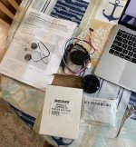
For my next trick I'm going to figure out these SmartCraft Trim Senders. The instruction booklet (yes, 14 pages just to install a trim sender :unsure: ) shows using the CDS G3 computer program to calibrate them. However, my weekly allowance does not support the cost of the CDS software/computer.

IMG_4673.JPG
.
I'm not a fan of these digital senders . . . the analog ones were so much easier to work with.

TIA for any tips/tricks or condolences . . . :rolleyes:
 
Last edited:
Top