sam am I
Commander
- Joined
- Jun 26, 2013
- Messages
- 2,169
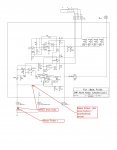
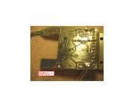
I put + probe on battery +, and negative probe on the bottom of the board, right around where the black arrow is in that picture. I did have to puncture the layer of laquer on the bottom of the board. Showed 12.48 volts, which is what the battery shows with meter hooked directly to battery.
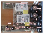
Then the red battery wire is open (or not connected properly to) somewhere from the battery + post and the soldered spade connector (battery +) seen in the pic's below, should be just a wire between your probes......


I'll try the light bulb test. Guess this would work with a regular test light, right?
*Yes, it should, assume you'd use standard incandescent type.
*Not going to work until we have the relays clicking when pinching the flex pot.
Lets try this approach............Place neg meter probe on battery - and meter probe + on same foil (battery+ soldered spades/black arrow foil again), what now?
Last edited:


