Minn Kota 3hp...anyone have one?

sam am I

Commander
Joined
Jun 26, 2013
Messages
2,169
Just to be clear, I should have 12V here right?

image_260188.jpg

Yes, you should diffidently have 12V at that point.........

I do not.

Smoking Gun!!

If that's where I need 12V I will try a jumper.

Yes.

Just don't want to fry anything.

You're good BUT, you have that 2'ish amp inline fuse installed? Right? Just as a per-caution, ya know :flame:

Could be a lurking solder splash, or...
 
Last edited:

jeepwm69

Petty Officer 3rd Class
Joined
May 26, 2010
Messages
84
PROGRESS! (I think).

Got my very shoddy soldering done this morning on a jumper wire.

Hooked up battery + and -, now get 12.XX volts at the diode, and when I pushed on the disk the relay clicks.

That's all I had time to do before work this morning, but will give it some time in the morning.

At this point should I hook it back up according to the wiring schematic and see if it works, or are there other things I should check first?
 

sam am I

Commander
Joined
Jun 26, 2013
Messages
2,169
PROGRESS! (I think).

Definitely HUGE move forward...

Hooked up battery + and -, now get 12.XX volts at the diode, and when I pushed on the disk the relay clicks.

Excellent!

should I hook it back up according to the wiring schematic and see if it works, or are there other things I should check first?

You could take a leap here BUT, considering the board is coming back from the grave, I'd typically approach it just a little more conservatively.

Also, I'm thinking it would be advisable to double check that all four driver FET's are still wired in parallel as per the design.

Lil background,

The high current motor driving capability of this board is quite dependent on the very low R(on) junction resistance of the FET transistors.

The manufacture's design calls for the parallel of four of the FET transistors to create theoretically an even lower effective R(on) total given by Rt(on) = 1/((1/(R1(on))+ (1/(R2(on))+ (1/(R3(on))+(1/(R4(on)))............Similar to resistors in parallel(in theory).

Although gm is a gentleman and a scholar to say the least, there might be a chance that there is a perhaps an addition disconnect lurking in the shadows.

If this is the case and a disconnect exists in the paralleled FET's config/requirement, it could cause a "situation" in that the effective R(on) will increase (see equation above less one or more R1-4(on)).

This will then causes a higher net voltage drop in the remaining paralleled FET's and at the fixed Rload (the motor), a higher voltage drop (V = IR) = more heat (P = IV) = POOF!


Given the above,

I'd recommend perhaps one or two baby steps testing solely the board up to it's limits before adding any other, although simple components, adding more variables such as switches, motors etc might overly complicate things if there are additional problems on the boards still. Suppose this way also, you'll additionally have another baseline to move up from.

As such and as it sits, I'd start by a lightly loaded test at this point which checks PWM IC and that the driver FET's are firing

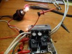
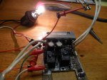
1) Hook up your automotive test lamp across the J2 (motor- ) and J5 (motor+), fire it back up and push on the flex pot in various places.

2) Verify the lamp goes from dim'ish to fully lit, note that U1-2 function is to set % Duty Cycle to 100% when pressing at bottom area of flex pot on both sides of Fwd and Rev pot area's. So depending on where you've pressed the pot, It should do this (respond essentially symmetrical) on both sides of the center point......Forward and Reverse.

3) Power off, set meter to ohms, review the schmatic, check from pin #6 of U2 to the gate (pin 1 see below) of each FET for 24.3 ohms.(R17, R18, R19, R20, See post #69 schematic)

4) Check for 0'ish ohms from each FET's source (pin 3 see below) pins to ground (J4, Ground/Battery -, See post #69 schematic).

5) Check for 0'ish ohms from each FET's drain (pin 2 see below) pins to J2 (motor -, See post #69 schematic).

If all is well,

6) Replace 2'ish amp fuse with 20 amp, repeat step #1, rinse lather repeat with a headlamp bulb ( i use a hi/low beam type with both beams wired together, think that's like 55W + 65W = 120W/12V = 10 Amps).

6a) Careful, the bulb gets mighty hot, ya might want to set it such that or clamp it somehow as not to burn down the house or you.

7) Let it run on full brightness (use a paper clip or something to hold the flex pot pinched) for say a 1/2hr or so.

If she runs cold'ish still (the heat sink on the FET's), wire up the motor and switch and fire it up..............
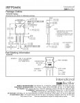
irfp044n.jpg
 
Last edited:

jeepwm69

Petty Officer 3rd Class
Joined
May 26, 2010
Messages
84
The bulb to J2 and J5 I get (dimmer vs brighter bulb depending on where pressure is applied).

The "FET transistors" I'm not so sure on. R17-20 are the "FET"s? And on which side am I measuring? (they look just like the diode D1 in the pic to me, but all these electronic components are foreign to me).

I'm having to work on this thing when time allows, so sorry to drag it out for as long as I have.
 

sam am I

Commander
Joined
Jun 26, 2013
Messages
2,169
The bulb to J2 and J5 I get (dimmer vs brighter bulb depending on where pressure is applied).

So cool.........

The "FET transistors" I'm not so sure on. R17-20 are the "FET"s? And on which side am I measuring? (they look just like the diode D1 in the pic to me, but all these electronic components are foreign to me).

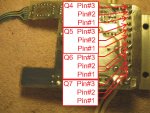
Apologies, The FET's are Q4, Q5, Q6, Q7 (See post #64)

3) Power off, set meter to ohms, review the schematic, check from pin #6 of U2 to the gate (pin 1 see below) of each FET for 24.3 ohms.(R17, R18, R19, R20, See post #69 schematic)

Following the above (step #3, post #103) quoted ohm measurement test, place AND KEEP the meter's + (or -) probe on pin #6 of U2 then place the meter's - (or +) probe directly and successively on EACH FET's pin #1 (see below pic) in turn measuring approx 23.5 ohms for each FET Q4-7.

A9R723F.jpg

Do the same for each "direct on the pin" test but follow step #4 (post #103) for each pin #3 ohm test and step #5 (post #103) for each pin #2 ohm from above.

I'm having to work on this thing when time allows, so sorry to drag it out for as long as I have.

Take your time, I'm not going anywhere, It's tax season.........

Most likely all is well and I'm perhaps being overly cautious and draggy myself BUT, it's only a few simple and quick tests that could spare a total melt down now or even in the future if there is an additional open we need to fix.

We definitely have beat it into submission to say the least and perhaps learned something too. That, in and of itself, is worth the extra time everytime IMO
 
Last edited:

jeepwm69

Petty Officer 3rd Class
Joined
May 26, 2010
Messages
84
I do not have power between J2 and J5.

The test light shows 12 V at each of those with the test light negative hooked to battery negative.

So it looks like both J2 and J5 are positive right now. Neither one is ground.
 

sam am I

Commander
Joined
Jun 26, 2013
Messages
2,169
I do not have power between J2 and J5.


You did once when you did the varying intensity test, post #104, right? Ya pressed on flex pot, relays clicked, lamp turned on, varied in intensity, you had power then.

These other post #106 measurements you made are? And why? Ya lost me........

I recommend just to complete #105 (continue on from your successful post #104 test) if those measurements/test pass, continue on and just hook up the motor and switch accordingly and go fishing............
 
Last edited:

jeepwm69

Petty Officer 3rd Class
Joined
May 26, 2010
Messages
84
Sorry about that. My post wasn't clear in 105. When I said I get that I met understand the concept.

When checking J2 and J5 with a test light I get nothing. Both have +12 V. Doesn't look like either of them ground.


You did once when you did the varying intensity test, post #104, right? Ya pressed on flex pot, relays clicked, lamp turned on, varied in intensity, you had power then.

These other post #106 measurements you made are? And why? Ya lost me........

I recommend just to complete #105 (continue on from your successful post #104 test) if those measurements/test pass, continue on and just hook up the motor and switch accordingly and go fishing............[/QUOTE]
 

sam am I

Commander
Joined
Jun 26, 2013
Messages
2,169
Sorry about that. My post wasn't clear in 105. When I said I get that I met understand the concept.

Ahhhhhh, crap, I misread that post, doh!!.....Moving forward then eh?

When checking J2 and J5 with a test light I get nothing. Both have +12 V. Doesn't look like either of them ground.


K, well, the relay's clicking tell me that the 12V supply to J5 is there, so that sounds good............

To get J2 to ground, the FET's need to turn on. To turn the FET on, U2 needs to turn on. To turn on U2, pin #7 should have 12V on it after the relays' click......To test,

Set meter to DC volts,

1) With - meter lead to battery -

2) Turn relay's on by pressing flex pot

3) Measure U2 pin #7 with meter + lead, what is the value?


Oh btw, your automotive test lamp lights up when you hook it across the battery in either direction? Just making sure its not polarized.

Also, while your there, might as well at this point.......With the relay's on (pressing flex pot), could you measure the dc voltage on all 8 pins on U2?

Pin #1 = ?
Pin #2 = ?
Pin #3 = ?
Pin #4 = ?
Pin #5 = ?
Pin #6 = ?
Pin #7 = ?
Pin #8 = ?
 
Last edited:

jeepwm69

Petty Officer 3rd Class
Joined
May 26, 2010
Messages
84
PN seven is about 2 V all the time and when I press the flex it goes up over 12

4- 4.18, goes to 5.27 pressing flex
3- .95goes to 1.28
2- 2.98 goes to 2.12
1- 1.76, goes to 1.67
8- 3v goes to 3.7
7- 2.7 goes to 12.05
6- 0 on both
5- 0 on both

I have to say the readings tend to jump around quite a bit.

When I rechecked them the second time some of the readings were slightly different but the pattern of up and down when I hit the flex seemed to be about the same one the particular pins.
 

jeepwm69

Petty Officer 3rd Class
Joined
May 26, 2010
Messages
84
PN seven is about 2 V all the time and when I press the flex it goes up over 12


1- 1.76, goes to 1.67
2- 2.98 goes to 2.12
3- .95goes to 1.28
4- 4.18, goes to 5.27 pressing flex
5- 0 on both
6- 0 on both
7- 2.7 goes to 12.05
8- 3v goes to 3.7


I have to say the readings tend to jump around quite a bit.

When I rechecked them the second time some of the readings were slightly different but the pattern of up and down when I hit the flex seemed to be about the same one the particular pins.

Edited to put them in order now that I'm not posting from my phone
 

sam am I

Commander
Joined
Jun 26, 2013
Messages
2,169
4- 4.18, goes to 5.27 pressing flex
3- .95goes to 1.28
2- 2.98 goes to 2.12
1- 1.76, goes to 1.67
8- 3v goes to 3.7
7- 2.7 goes to 12.05
6- 0 on both
5- 0 on both

Hmmm.

Measurements with flex not press to flex pressed on a working board...............
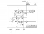
1 - 0.65V to 1.50V - 3.00V (flex area press dependent)
2 - 2.10V to 2.50V
3 - 0.00V to 0.40V
4 - 0.00V to 2.00V
5 - 0.00V to 0.00V
6 - 0.00V to Varies (PWM/meter bandwidth dependent)
7 - 0.00V (C4/5 fully discharged) to 12.00V Vbatt.
8 - 0.00V to 5.00V


gm, you said "planned to change" U2 in post #18, were you able to replace the U2/UC3842?

Jeeps readings (esp pin's #3, #4[flex not pressed] and Pin #8 [not pressed/pressed]) appear to indicate the IC is smoked.


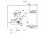
R12 to Pin #2 U2 fix in Rev 1.3 below.


ExpressSCH Rev 1_3.jpg
 
Last edited:

sam am I

Commander
Joined
Jun 26, 2013
Messages
2,169
jeep, it's looking like "now is ze time on Sprockets vhen ve dance!"

Thinking I might be a bit more set up to replace IC's and such, unless you want to learn? I have a few learning/how to links and you'll need a bit of solder wick, iron, solder and a new UC3842 to replace U2.

I certainly could be wrong about the IC-U2 being bad but, those measurements seem way off, esp. if when 12V is on pin #7, pin #8 isn't 5V spot on! Pin #8 absolutely is to have and is internally designed to be 5V @ 1mA when the IC is powered up else the IC is shot, or the pin is somehow loaded down as its driving out into shorted'ish/bad components/traces (il > 1mA) but, the board is so simple, I'm leaning towards the IC simply being bad.

Else.......

We could swap boards? Once received, I'll swap your flex for mine (mine is repaired and works fine but if yours isn't cracked, I'd prefer you keep yours) I'll send you back my board with your flex.......I'll then fix your board and post the fix to close this jumbo thread.


It's your call jeep, pm me if you want to swap boards,
 
Last edited:

jeepwm69

Petty Officer 3rd Class
Joined
May 26, 2010
Messages
84
jeep, it's looking like "now is ze time on Sprockets vhen ve dance!"

Thinking I might be a bit more set up to replace IC's and such, unless you want to learn? I have a few learning/how to links and you'll need a bit of solder wick, iron, solder and a new UC3842 to replace U2.

I certainly could be wrong about the IC-U2 being bad but, those measurements seem way off, esp. if when 12V is on pin #7, pin #8 isn't 5V spot on! Pin #8 absolutely is to have and is internally designed to be 5V @ 1mA when the IC is powered up else the IC is shot, or the pin is somehow loaded down as its driving out into shorted'ish/bad components/traces (il > 1mA) but, the board is so simple, I'm leaning towards the IC simply being bad.

Else.......

We could swap boards? Once received, I'll swap your flex for mine (mine is repaired and works fine but if yours isn't cracked, I'd prefer you keep yours) I'll send you back my board with your flex.......I'll then fix your board and post the fix to close this jumbo thread.


It's your call jeep, pm me if you want to swap boards,

My soldering skills typically involve burning myself, lots of cussing and wasted solder, and a connection that comes apart the first time there is any vibration or movement.

I would be happy to send you the board, and you can either swap out or send mine back.

I have another trolling motor to use, just hated to throw this one out. Point being, you can take your time either way.

If you'll pm me your address I'll drop it in the mail.

Thanks to both you and gm for all the time you've spent on this old motor. I bought it when I was 12 or 13, and had to save a LONG time to be able to buy it. Have a lot of fond memories using it and while I know a new motor is cheap, I just didn't want to toss this one if it could be fixed.
 

sam am I

Commander
Joined
Jun 26, 2013
Messages
2,169
Haven't got your board yet jeep BUT a voice in my head (have several) went off this morn........Waaaaaaay back there gm said that he planned on replacing U2 and I think he said he thought it was a UC3842.

I double checked my board just now and it has a UC3843...........
If using a UC3842, it'll require at least 16V initially on pin #8 else it'll stay in UVLO, "undervoltage lock out" forever............Using then a 12V battery/designed TM and reviewing the IC's design, my guess here then is this is why your pin #7 never fired up to a stable state of 5V and all your measurements around the IC were all in indeterminate/standby states.

Data sheet here

A UC3843 requires only 8.5V to come up and out of UVLO.

Super easy fix if this is the case, have some 43's laying around here somewhere. I'll also update drawing (Rev 1.4) to include this as well.
 
Last edited:

sam am I

Commander
Joined
Jun 26, 2013
Messages
2,169
Correction to above.............."16V initially on pin #7 else it'll stay in UVLO"
 

jeepwm69

Petty Officer 3rd Class
Joined
May 26, 2010
Messages
84
Board and switch went out Friday afternoon, and I included a return label.

I would love to see what you find when you check it out. Feel free to make fun of my soldering job on that jumper wire too.

I'm good with a wrench, but with electrical stuff, not so much. LOL
 

sam am I

Commander
Joined
Jun 26, 2013
Messages
2,169
Very good, will let you know when received and yes, I'll definitely will let you know what I find.

I might tease you on the solder job but, like most everything else, it's a learned thing so I'll go easy........

I'm also going to update the drawing Rev. from 1.3 to 1.4 here reflecting the U2 change from the UC3842 to the UC3843. I'm going to assume this is the case due to the fact my board has a factory installed UC3843.

ExpressSCH Rev 1.4.jpg
 

sam am I

Commander
Joined
Jun 26, 2013
Messages
2,169
Received board,

Two things,

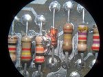
1) Removed solder bridge that was shorting across Pin 7 U3/cathode D3 and Pin 4 U2/R9/C2 nodes, that took down oscillator.

No oscillator, no work at any voltage.........

SAM_0364.JPG


2) Board powers up/PWM circuity all works fine BUT requires 16+ V applied due to U2 is UC3842 (stays in UVLO if Batt < 16V).

SAM_0372.JPG SAM_0371.JPG


Switch checks good, FET's all in check in parallel. I'll get U2 swapped out to UC3843, load it down with 10'ish amp @12V for 1/2hr or so test and ship it back jeep.

Oh and I'll spruce up your jumper ;)
 
Last edited:
Top