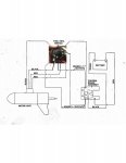
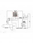
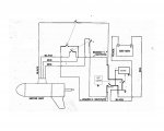
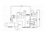
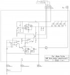
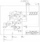
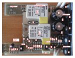
Sam the schematic diagram I was referring to was for the actual circuit board. But anything is a help at this stage. Again, so hard to trouble-shoot via comments.
Great news! Brenda at Minn Kota found me a diagram for the switch. I'll get things hooked back up this weekend and hopefully will have this one ready to be used again!
I will say I'm not 100% sure that the switch is good. That's why I started with taking measurements there.
Haven't forgotten about this, just had a really hectic few days.
I'll try to get back into it over the weekend and report back.
Thank yall for the help. I appreciate both of you taking the time to weigh in.
Not sure how it all is connected because I figured once all the burnt parts were replaced, it would be fixed. If I would have traced al the runs and had all the needed parts to assembly it to one of my TM's, I could have headed off any more problems. But as the saying goes, that is now water under the bridge.
Obviously the twist switch isn't handling any real amount of current and there for all the other parts are doing that. So again, I would love to see a real schematic diagram for this circuit board. JMHO
Don't sweat the small stuff gm, this is a great learning tool. I'm glad you didn't!!
The encoder/pot on the flex ribbon cable isn't, agreed BUT, the main switches internal to the housing when the handle is twisted, are, right?
If the switch is connected via the flexible PC film, It isn't handling any amount of current, it literally can't. I would melt that flex board instantly. So everything from the switch set up has to be controlling the real current handling parts on the PC board. JMHO
The "ground foil" is actually the ground traces remaining on any circuit board. And lots of time they manufacture circuit boards with a lot of ground material remaining on the board to help with noise rejection and save on acid material used to remove it. So the majority of the metal material remaining on this circuit board is a ground. So take a meter set to resistance and verify you have continuity between the top side and bottom side of the ground material.
So test this area with an area like it on the bottom to verify they read zero resistance....or very very close to zero. Test it with this bottom side
Post your results.
Got my new multimeter yesterday. Checked the bottom of the board with neg probe, while + probe was on battery +. Got full voltage reading so the "ground foil" does appear to be grounded.
Still nothing when I check pins 5 and 7.
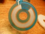
On the plastic bit that sits up against the ribbon/disc thingy, there are three points that press against the ribbon. I assume these make a connection with pressure, correct?
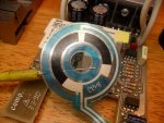
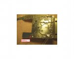
This "ground foil"?
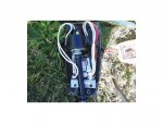
Pic A
If so, No! That foil is directly connected (or suppose to) to the battery +...........It ISN"T ground, the black text is incorrect.
If you had your neg probe - on that foil area while the pos probe's + is connected to the battery +, then your reading should (has to be if connected properly) be 0'ish volts. It's a wire between the two testing points you used/listed.
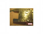
Pic B
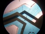
.
Follow the red wire seen above (see pic B) and where it connects to the board and look at my red boxed labels on both the above pic's............see?
They are (or suppose to be) the same points. Note that the red battery cable...........It hooks up the the board's spade connector and is solder directly (on the back side of the board) to that same foil in pic A above.....
The ground foil is mainly on the top of the board.......And again, but following black wires (see pic B) this time....THIS is a/your ground (battery -) test point (see pic C below) on the bottom side of the board.
Pic C
Correct.......Not until the throttle rotates on/about the flex face and off the center point (neutral/off position) should the relays turn on (you'll hear them click) and THEN the voltage will then be present on pin 7 UC3842. Drawing and theory of operation to follow in day or so.
Yes.......and using your finger nail, etc to press in of the flex will suffice as a substitute method to activate the comparitor (turn relays/power on the pin #7) if throttle isn't assembled.