LiFePO Batteries ???

tpenfield

Moderator
Staff member
Joined
Jul 18, 2011
Messages
18,063
Ok, so what solar panel & controller configuration would work for this situation?

That‘s what I am trying to achieve.

Thank you.
I might have answered my own question . . . it looks like when using both Li and AGM in the same system with solar charging, the preferred method is to solar charge the Li and use a DC-DC converter to charge the AGM from the Li. The reason being that the resting voltage of the Li is about 1.0 volt higher than the AGM.

Still reading up on this approach . . .
 

tpenfield

Moderator
Staff member
Joined
Jul 18, 2011
Messages
18,063
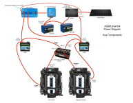
OK after some research, here is what I am thinking (hoping) will work . . .

  • The solar panel charges the LiFePO4s
  • The LiFePO4s charge the AGMs (when engines are not running and solar power is creating enough voltage)
  • Alternators charge AGMs and LiFePO4s via the dual input charger when the engines are running.
.
Power-Diagram-Key-Components-1.png
 

bruceb58

Supreme Mariner
Joined
Mar 5, 2006
Messages
30,543
That's better. However, I would skip both isolators. Just put an ACR between the two AGM batteries. Run the output of the DC to DC converter to just one of the batteries. Basically, once it gets fully charged enough that the voltage hits the ACR trigger voltage, then the two batteries will connect.

In my brother's class A motorhome, I put in a 12A Victron Orion DC to DC converter to keep his chassis battery bank charged. I set up the converter to only come on once the lithium batteries(charged with solar) hit a voltage of 13.8V and turned off at around 13.3V or so. This way, the lithiums would get fully charged before the DC to DC tried to send a charge to the chassis batteries. What happens is the DC to DC ends up turning on and off a lot until the chassis batteries got fully charged.
 
Last edited:

bruceb58

Supreme Mariner
Joined
Mar 5, 2006
Messages
30,543
You may actually want to just put a cheap solar controller to keep the AGM batteries charged. Put a DC to DC converter between the AGM and the lithium but keep the turn on voltage high enough so that the DC to DC only comes on when the engine is running.

Lithiums do not care how fully charged they are so you can store them, in fact it is preferred, to store them at around 60% charge.

The scenario that I don't understand is when do you need your lithiums fully charged...at the dock with shore power or underway? Just sitting at a place relying on solar won't do much for them anyway and its not really needed.
 

tpenfield

Moderator
Staff member
Joined
Jul 18, 2011
Messages
18,063
You may actually want to just put a cheap solar controller to keep the AGM batteries charged.
I have the 10 amp Voyager solar controller, but not sure if it should be connected to the solar panel in parallel to the DC/MPPT converter. I think the Voyager is low tech (PWM). (I wonder if it is the source of the 30% power loss that I am seeing with the existing system?)
 

tpenfield

Moderator
Staff member
Joined
Jul 18, 2011
Messages
18,063
I also put the design question out on a DIY Solar forum to see what I get for comments.
 

tpenfield

Moderator
Staff member
Joined
Jul 18, 2011
Messages
18,063
Just reading up on the Renogy Dual Input DC-DC w/ MPPT unit . . . it favors the Service battery (LiFePO4 in this case) until it is charged, then will trickle charge the starter battery when on just solar (engine not running).

That may suffice to keep the starter batteries charged while the boat is not in use. So, I may not need the second converter in the diagram.
 

bruceb58

Supreme Mariner
Joined
Mar 5, 2006
Messages
30,543
The reason you lose 30% with a PWM is because the max charge current you can get is the max current that the panel can put out. An MPPT can in theory get 100%.

Let's say you have a 100W panel that has the specs 20Vmpp and 5Ampp. With the PWM, the most power will be 5A x charge voltage which might be 5x13=65W. AN MPPT can get the full 100W if the panel is aimed correctly since it does a DC to DC conversion.

You can never have a panel drive an MPPT and another controller. The reason is because the MPPT occasionally does a power sweep where it changes it's input impedance to determine the max power point combo of voltage to current coming out of the panel. In some instances, it will actually short out the panel completely during this power sweep. If there is another controller on the MPPTs input, it could either wipe out the other controller or neither would work properly.

I probably know the DIY solar forum you are posting on. Probably 20% of the people will the knowledge to actually help you. The problem will be knowing who those 20% really are!
 
Last edited:

bruceb58

Supreme Mariner
Joined
Mar 5, 2006
Messages
30,543
Just reading up on the Renogy Dual Input DC-DC w/ MPPT unit . . . it favors the Service battery (LiFePO4 in this case) until it is charged, then will trickle charge the starter battery when on just solar (engine not running).
That is incorrect. It only has one output.

The outputs of two solar controllers can be put in parallel...not the inputs. Some controllers may get turned off once they sense the output voltage of the other.
 
Last edited:

tpenfield

Moderator
Staff member
Joined
Jul 18, 2011
Messages
18,063
That is incorrect. It only has one output.

The outputs of two solar controllers can be put in parallel...not the inputs. Some controllers may get turned off once they sense the output voltage of the other.
Just going by what I read in the Renogy manual . . .
Renogy-Manual-Cover-Page.png

Here are the key features that they list:

"The Renogy Dual Input DC-DC On Board Battery Charger w/ MPPT is designed to charge your service battery to 100% from two inputs: solar and alternator. Featuring multi-battery compatibility including Lithium, this DCDC utilizes alternator power, solar power with MPPT technology, or both to make sure that you're always charged and can enjoy being off the grid longer!

Key Features

  • Designed to charge service batteries from two DC inputs—solar panels and alternator Built-in Maximum Power Point Tracking (MPPT) to maximize the solar power
  • 3-phase charging profile (Bulk, Boost, and Float) ensures your service battery will be accurately charged at the correct voltage levels to 100%
  • Compatible with smart alternators (with variable output voltage)
  • Trickle charges the starting battery via solar panels if the service battery is fully charged
  • Isolation of the starting battery and the service battery
  • Temperature and voltage compensation features prolong battery life and improve system performance
  • Smart Protection Features: battery isolation, over-voltage protection, battery temperature protection, over-current protection, overheat protection, reverse current protection, solar panel and alternator reverse polarity protection
  • Compatible with multiple battery types: Sealed, AGM, GEL, Flooded, and Lithium Compact with a sturdy design, it was built tough for all conditions"
Maybe the 'trickle charge' is only a smart alternator feature, but I'll test it out . . .

I probably know the DIY solar forum you are posting on. Probably 20% of the people with the knowledge to actually help you. The problem will be knowing who those 20% really are!

Yes, that is true on many forums. I'm on a couple of upholstery forums and there seems to be a dozen stated ways to do anything, so you have to figure out things for yourself in many cases.
 

tpenfield

Moderator
Staff member
Joined
Jul 18, 2011
Messages
18,063
A few things that I need to be mindful of is that the boat uses power when sitting at the mooring (or in the driveway for that matter). All small amounts of power, but they can add up over time. . . Xantrex, Stereo, Mercathodes.

I also need to be mindful about the Mercruiser Smartcraft system, as that is voltage sensitive, and I had voltage warning/faults during my first year with the boat. That was my original incentive to add the 100 watt solar system.

I've also been chasing an electrical gremlin where the Smartcraft 'system voltage' thinks it is higher than what it 'sees' as the battery voltage.

A few folks over on the DIY Solar forum have suggested charging the LFP's from the AGM's via DC-DC converters. But to me the resting voltages of each battery type would mean that the voltage would have to 'climb uphill' (as I put it) going from about 12.7V (AGM) to 13.2V (LFP). I'm not sure if/how DC-DC converters handle an input voltage being lower than what is needed on the output. (I'll have to read up on the converter's specifics).

So in that scenario, it may be a matter of charging the LFP's only when the engines are running (or on shore power) and the voltage at the AGM's are more in the 13.5-14.0V range.

Anyway, my head is starting to hurt, but I think I'll read up on some more off-grid system designs containing both AGM and LFP . . . with solar.
 

tpenfield

Moderator
Staff member
Joined
Jul 18, 2011
Messages
18,063
OK . . . DC-DC converter steps up the voltage via a "Boost Converter Circuit" not sure about DC 'chargers' vs. 'converters' :unsure:
 

bruceb58

Supreme Mariner
Joined
Mar 5, 2006
Messages
30,543
That's interesting about the trickle charger of the starter battery. It would have to charge it out its normal DC to DC input.

Yes..the input of a DC to DC converter can be lower than the output. That's the beauty of a DC to DC converter and why I use one to charge from my vehicle to my travel trailer.

As far as DC to DC converters/chargers. Typically, they are chargers but there are a few that convert only. For example, if you have a 24V battery system and you need to power existing 12V items, you would buy a 24V to 12V DC to DC converter without a charging function...it would be a fixed voltage.
 

bruceb58

Supreme Mariner
Joined
Mar 5, 2006
Messages
30,543
This is an option for a dual output solar controller. Epever is not a bad brand. I actually use one for keeping my truck topped off when sitting. One output which is high current is for lithium or lead acid and the 1A output is for lead acid only. I could not find a spec for the trickle charge output for the Renogy unit.


tpenfield

Moderator
Staff member
Joined
Jul 18, 2011
Messages
18,063
I like the dual charge controller approach. It seems like product evolution is trying to keep up with various system design challenges.

Looks like most 'chargers' have boost capabilities. I'm not liking the Renogy DC-DC charger specs as the spec for idle current is pretty high.
 

bruceb58

Supreme Mariner
Joined
Mar 5, 2006
Messages
30,543
Are your Mercathodes on the engine battery or house? Do you turn your battery switches off when you leave the boat?
 

tpenfield

Moderator
Staff member
Joined
Jul 18, 2011
Messages
18,063
Are your Mercathodes on the engine battery or house? Do you turn your battery switches off when you leave the boat?
I believe the Mercathodes are on the engine batteries.

The battery switches (4 of them) are in the engine bay and if you shut the house battery off, then you cannot close the engine bay/hatch. So, shutting things off is not very practical (unlike my previous boat). . . . nor would you want to shut off the engine batteries because of the Mercathodes.

The plan would be to provide enough maintenance charge to keep the batteries charged. The AGM's certainly would need more than the LFP's in that regard, but the Xantrex unit will draw some standby/idle current.
 

bruceb58

Supreme Mariner
Joined
Mar 5, 2006
Messages
30,543
I believe the Mercathodes are on the engine batteries.

The battery switches (4 of them) are in the engine bay and if you shut the house battery off, then you cannot close the engine bay/hatch. So, shutting things off is not very practical (unlike my previous boat). . . . nor would you want to shut off the engine batteries because of the Mercathodes.

The plan would be to provide enough maintenance charge to keep the batteries charged. The AGM's certainly would need more than the LFP's in that regard, but the Xantrex unit will draw some standby/idle current.
I have the Mercathode system and they get their power directly from the battery so that I can turn off my battery and still have power to it. Same applies to my bilge pump.

On Cobalts, battery disconnect is outside the engine bay so boats with power hatches don't have your issue. Seems counterintuitive that your boat does it that way.

Your Xantrex should either have it's power switched off to it or have it go into a non powered mode with a remote control panel. My Inverter in my trailer consumes ZERO power when I turn it off with my small control panel.
 

tpenfield

Moderator
Staff member
Joined
Jul 18, 2011
Messages
18,063
The folks over at the DIY Solar forum are arguing among themselves. So, I'll let that go. Meanwhile, I have been contemplating a couple of approaches . . .
  1. Charge the AGM's and let the AGM's charge the LFP's
  2. Charge the LFP's and let the LFP's charge the AGM's
I've been back & forth on this a couple of times, but it may be easier to do #1 . . . Each approach would require a controller and a charger to get the full functionality that I'm looking for.
 

tpenfield

Moderator
Staff member
Joined
Jul 18, 2011
Messages
18,063
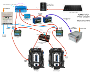
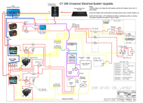
Here are my latest design diagram & schematic, including the shore power. I am going to let the ProNautic charge just the AGM's and the Xantrex charge the LiFePO4's, since the Xantrex has an 80 amp charge capacity.
.
Power-Diagram-Key-Components-1E.png
.
CY-338-Power-Diagram-2024Mod5E.png
.
I've been back & forth on LiTime and ExpertPower battery brands. Both seem to be fairly decent mid-tier battery brands. LiTime has recently added cold temperature protection to their 100 Ah model.

I'm upgrading the solar controller to an MPPT variety, staying with Renogy, since the solar panel is renogy. In my Googling and You Tubing, I've come to understand that the flexible panels (which I have) do not last as long as the rigid panels.

The DC-DC Charger is going to be Victron Smart Tr 12-12/30 . . . There is a new series (Orion XS) that has recently been announced, so I may go with that model if it is readily available. The 'Smart Tr' models are known for heat/cooling issues.
 
Top