Fuel pump no power/ relay to pump help

Fun Times

Moderator
Staff member
Joined
May 16, 2009
Messages
9,014
My 1998 Volvo powered boat has a lanyard. I always thought it was required by law on boats going back to the mid 80's at least.
The laws on making one use the lanyard as mandatory are still up in the air expect for Alabama.

Looks like it became a requirement for boat manufacturers to "install" them in 06.
1-4 April 2006 NBSAC passed Resolution Number 2006-77-02 (Boat Builder Engine Cut-off Switch Installation Requirement) and Resolution 2006-77-4 (Required Use of Engine Cut-off Switch Link).
If interested, Here's a pretty good rundown of the history of the lanyard switch mostly starting in late 1973 for a patented recreational boat use.....Scroll down a bit for the timeframe rundown history. http://www.propellersafety.com/3913/regulations/kill-switch-history/
 

flyhigh123

Petty Officer 2nd Class
Joined
Nov 17, 2012
Messages
112
got to thinking, i wonder if the ignition switch died on me.... maybe the on position is dead...
 

Fun Times

Moderator
Staff member
Joined
May 16, 2009
Messages
9,014
got to thinking, i wonder if the ignition switch died on me.... maybe the on position is dead...
That was one of my first thoughts when you mentioned it would run while holding the key over to start in post 54. Try jumping the wires behind the key switch to see if it helps. Connect Red to Purple then touch Yellow/Red to Red till started and release.
 

flyhigh123

Petty Officer 2nd Class
Joined
Nov 17, 2012
Messages
112
That was one of my first thoughts when you mentioned it would run while holding the key over to start in post 54. Try jumping the wires behind the key switch to see if it helps. Connect Red to Purple then touch Yellow/Red to Red till started and release.
Will go today. Read the manual and it also gives advice on checking the ignition switch. Will check continutity for both points. After that, i will jump the wires and see. Boat goes to shop on Monday, so hopefully i can solve this before hand.
 

bruceb58

Supreme Mariner
Joined
Mar 5, 2006
Messages
30,530
Don't measure continuity. You have to take wires off to do that. Just measure the voltage.
 

flyhigh123

Petty Officer 2nd Class
Joined
Nov 17, 2012
Messages
112
Update:

Ignition seems ok. Continuity check seems to work for key switch. It didnt read zero, but read around 100 for ON position.

I did jump a 12V source from POS on alternator directly to the bunch of wires which includes the green wire and the engine fired up and ran . So it seems the issue now is somewhere between the ignition to bunch of wires/ alternator.

I also got the alternator in today from iboats. Is the alternator something straight forward for install? If I were to put it in myself, can you guys help suggest which color goes to which letter.

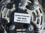
The back of the alternator has the following letters:
L2
P
E ( bottom Right)
EXC
S
B ( letter under the black wire upper left)


I have the following wires:

Orange ( this is 12V)
Red/purple
Red
Purple/White
Black
Green


Assuming the diagram is correct I have the following:

Orange->P
Red/Purple -> S
Red-> ExC
Purple/White ->?
Black->Ground ( is the ground the peg between B and E or is it B?
Green-> L2

Let me know if this is correct and what I'm missing.

Thanks!
image_240357.jpeg
 
Last edited:

bruceb58

Supreme Mariner
Joined
Mar 5, 2006
Messages
30,530
You don't have it correct.

It should be:

B is the wire that goes to the battery(Thick Orange)
P is the AC tap and that goes to the choke(Purple/White)
E is ground(Black)
EXC and S should be tied together and that goes to your ignition switch(purple or red/purple)
L2 goes to the Fuel Pump relay(Green)

You may have to make up a jumper to connect the excite(EXC) and the Sense(S). Don't run until you get those 2 jumpered or you will fry your new alternator.

Look at fun times picture in post#3. Even though it is not an OEM picture it's basically correct.
 
Last edited:

flyhigh123

Petty Officer 2nd Class
Joined
Nov 17, 2012
Messages
112
You don't have it correct.

It should be:

B is the wire that goes to the battery(Thick Orange)
P is the AC tap and that goes to the choke(Purple/White)
E is ground(Black)
EXC and S should be tied together and that goes to your ignition switch(purple or red/purple)
L2 goes to the Fuel Pump relay(Green)

You may have to make up a jumper to connect the excite(EXC) and the Sense(S). Don't run until you get those 2 jumpered or you will fry your new alternator.


The Red is the jumper for the EXC and S. Thanks for the clarification. The alternator didnt come with any manual.
 

bruceb58

Supreme Mariner
Joined
Mar 5, 2006
Messages
30,530
I have no idea why you have both a red and a red/purple wire. You may want to investigate which one gets voltage on it with the ignition both in the on position and off.

EDIT: Just saw your post.
 
Last edited:

flyhigh123

Petty Officer 2nd Class
Joined
Nov 17, 2012
Messages
112
I have no idea why you have both a red and a red/purple wire. You may want to investigate which one gets voltage on it with the ignition both in the on position and off.

EDIT: Just saw your post.
Per the diagram, i think that it is correct. Red Goes from EXC to S and Purple goes to S. Its just 2 cables, but the S terminal has 2 wires.
 

flyhigh123

Petty Officer 2nd Class
Joined
Nov 17, 2012
Messages
112
put in the alternator. looks really nice and feels good to have all the wires go to the correct location. However, didnt fix issue. Boat still will not idle in On position, it will idle in Start position.

Waiting for room at the mechanic. Tomorrow i will meter the 12v at ignition switch.
 

bruceb58

Supreme Mariner
Joined
Mar 5, 2006
Messages
30,530
Just with the ignition key on, and doesn't matter if engine not running, it should be 12V. Basically, if you get 12V at your ignition switch, you should get 12V at the excite.
 

flyhigh123

Petty Officer 2nd Class
Joined
Nov 17, 2012
Messages
112
Tested the Ignition key at ON, it read 12V.

Went to the Excite with key ON, and it read 0V.

The problem seems to be somewhere in between. What would you suggest the next step be? Can I run a new wire from the ignition to Alternator?
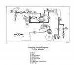
Charging System 7.jpg
 

Attachments

  • Charging System 7.jpg
    Charging System 7.jpg
    308.2 KB · Views: 2

bruceb58

Supreme Mariner
Joined
Mar 5, 2006
Messages
30,530
Are you absolutely positive you don't have a man overboard switch somewhere?

Try following the wire leaving the ignition switch and see how far you get with it. Maybe it goes back to your fuse panel and picks up another fuse.

Make sure your engine connector is fully engaged. You can also pull apart the engine connector and see if you get voltage there.
 
Last edited:

Fun Times

Moderator
Staff member
Joined
May 16, 2009
Messages
9,014
Try ohms checking the purple wire from the key switch to the Alternator purple wire and see what you get...Next you have a main wiring harness cannon plug connector at the engine, remove and inspect the pins on both sides.

With the meter still connected to the purple wire at the key, ohms check all the wires at the boat side plug to ensure you get a good ohms reading to only one of the wires. Now ohms check the wire between the engine harness plug to the purple wire at the Alternator. The purple wire pin harness should be pin number 5 like seen in post number 3. Also be sure to wiggle the harness as it could be a bad connection inside the plug somewhere.
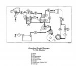
Bringing the diagram over here so it's easier to see vs post #3.

2013-05-14_043617_scan0002.jpg
 

flyhigh123

Petty Officer 2nd Class
Joined
Nov 17, 2012
Messages
112
Are you absolutely positive you don't have a man overboard switch somewhere?

Try following the wire leaving the ignition switch and see how far you get with it. Maybe it goes back to your fuse panel and picks up another fuse.

Make sure your engine connector is fully engaged. You can also pull apart the engine connector and see if you get voltage there.

Yes no man overbaord switch.
 
Last edited:

flyhigh123

Petty Officer 2nd Class
Joined
Nov 17, 2012
Messages
112
Try ohms checking the purple wire from the key switch to the Alternator purple wire and see what you get...Next you have a main wiring harness cannon plug connector at the engine, remove and inspect the pins on both sides.

With the meter still connected to the purple wire at the key, ohms check all the wires at the boat side plug to ensure you get a good ohms reading to only one of the wires. Now ohms check the wire between the engine harness plug to the purple wire at the Alternator. The purple wire pin harness should be pin number 5 like seen in post number 3. Also be sure to wiggle the harness as it could be a bad connection inside the plug somewhere.
Bringing the diagram over here so it's easier to see vs post #3.

2013-05-14_043617_scan0002.jpg

Is the "main wiring harness cannon plug connector at the engine" the Main Cable connector on the diagram? I have a black rectangular box which i'm assuming is the cable connector. I'll try what you are saying. Should i open the cable connector box and test from inside?
 
Top