Custom Fiberglass Extended Swim Platform

tpenfield

Moderator
Staff member
Joined
Jul 18, 2011
Messages
18,085
I was able to get an inner tube in the gap and put some pressure in it. The mold is a lot stronger than the plug, as I managed to crack the plug :eek:

I may end up flipping the whole thing over and taking the plug out in pieces :rolleyes:
 

froggy1150

Master Chief Petty Officer
Joined
Nov 3, 2017
Messages
852
Don't know if this will work but what if you put a air regulator on your vacuum lines and put some positive pressure on them when you pry. Maybe 20 psi????
 

tpenfield

Moderator
Staff member
Joined
Jul 18, 2011
Messages
18,085
SUCCESS !!! :D

I tried drilling a hole from the underside of the plug just into the fiberglass and see if I could get some compressed air in there (60 psi) No luck.

I managed to get the forward edge up far enough that I could put a long piece of hardwood in to the step-down area and used that as a wedge. A few whacks with the hammer along the length of it and it sprung loose :)

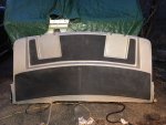
Overall, it looks OK . . .
IMG_2360.JPG
.
Much of the flange area separated as I wedged the perimeter loose. I didn't really think the mold would have such a grip on the plug. The worse area was along the step-down portion . . . like a death grip :rolleyes:

Tomorrow will be inspection and touch-up. I'm on schedule :thumb:
 

Attachments

  • IMG_2361.JPG
    IMG_2361.JPG
    170.8 KB · Views: 6
  • IMG_2362.JPG
    IMG_2362.JPG
    143.4 KB · Views: 5
  • IMG_2363.JPG
    IMG_2363.JPG
    163.5 KB · Views: 5
  • IMG_2364.JPG
    IMG_2364.JPG
    201.8 KB · Views: 5
  • IMG_2365.JPG
    IMG_2365.JPG
    294.5 KB · Views: 5

Scott Danforth

Grumpy Vintage Moderator still playing with boats
Staff member
Joined
Jul 23, 2011
Messages
49,850
Looks great.

Maybe use more wax and pva when you make parts
 

oldrem

Commander
Joined
Nov 7, 2013
Messages
2,002
Getting there - you'll have stories to tell for years once it's all done
 

tpenfield

Moderator
Staff member
Joined
Jul 18, 2011
Messages
18,085
Weekend update . . .

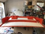
While the gelcoat touch-up areas are curing, I mapped out and cut the foam core strips for the platform.

Click image for larger version  Name:	IMG_2367.JPG Views:	1 Size:	184.4 KB ID:	10721855
.
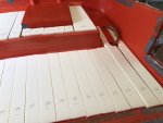
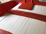
The core is going to be a series of beveled urethane foam strips. Each piece is numbered as to where is goes in the platform.
.
Click image for larger version  Name:	IMG_2369.JPG Views:	1 Size:	124.4 KB ID:	10721856
.
Click image for larger version  Name:	IMG_2368.JPG Views:	1 Size:	141.2 KB ID:	10721857
.
There will be fiberglass cloth interwoven among the strips, forming a structure similar to corrugated cardboard. The structure is also referred to as a 'navtruss'.

I'm planning on the platform being about 3/4" thick typical. The foam core is 1/2" and there will be about 1/4" total of fiberglass (1/8" top & bottom of the core).
.
image_310306.jpg
.

I was thinking of adding a layer of 24 oz WR to each top & bottom laminates, just to beef it up a bit more.

Any thoughts on this ??? :noidea:

Overall, I'm looking for strength/stiffness while being light weight.
 

tpenfield

Moderator
Staff member
Joined
Jul 18, 2011
Messages
18,085
In other news . . .

I ran a 'pot life' test of the VE resin that I will be using for the platform.

The resin is "AOC Vipel F010-TBN-23" what ever that means . . . :noidea:

I did 3 tests of different catalysts/inhibitor mixes. . . each 3/4 ounce in a medicine cup, Starting temperature was 59˚ F.

1) MEKP @ 2% Time to Gel was 40 minutes, peak exotherm temp was 235˚ F :eek:

2) MCP @ 2% Time to gel was 90 minutes, peak exotherm temp was 70˚ F

3) MEKP @ 2% + TBC Inhibitor @ 300 ppm. Time to Gel was 65 minutes, peak exotherm temp was 240˚ F :eek:

I'm inclined to use the MCP catalyst rather than any of the MEKP combinations. The MEKP combinations, both with and without inhibitor did not cure well, probably because of the excessive heat.
 

kcassells

Fleet Admiral
Joined
Oct 16, 2012
Messages
8,737
I love the work and precision. I could not ever do that.
tenor.gif
 

tpenfield

Moderator
Staff member
Joined
Jul 18, 2011
Messages
18,085
I'm still thinking about the reinforcing around the inside of the aft perimeter. I need to have a vinyl foam board backing material for the rubrail on the outside perimeter to screw into. I also need to provide some thickness around the perimeter for strength.

Also, I have been figuring out the amount of resin to prepare for the infusion, I have done some refinements to my guesstimations. On the platform mold, I prepared 3 gallons of poly resin for the infusion. I will be doing the platform part itself with 2 separate infusions, with a hand layup and vacuum bagging of the core material. I need to plan out the resin for all 3 steps.

Here are the calculations that I have come up with so far, which I thought to share in case anyone is considering vacuum infusion.

The approximate sq footage of the part in all of its shape complexities is 44 sq. ft.

The initial infusion will be with the following layers of material and their associated thickness under compression (vacuum):

CSM (0.019")
1708 (0.027")
1708 (0.027")
WR (0.029")

The total is about 0.102" thickness for the outer layer of glass, which goes in the mold first, after the gelcoat has initially cured.

The 'volume' in the mold under vacuum will be as follows:

( 44 sq. ft. X 144 sq in/sq ft X 0.102 in. ) / 1728 cu. in/cu ft X 7.48 gals./cu. ft = 2.79 gallons (volume of the mold)

figuring the resin/cloth ratio will be about 50/50 for vacuum infusion, The volume of resin in the mold will be:

2.79 gallons X 0.50 = 1.40 gallons

Generally you would add 20-30% more resin for safety and loss through the distribution runners. So, I'll be preparing 2 or maybe 2.5 gallons of resin for the first infusion.

The second infusion may be a wee bit thicker than the first infusion, so that may get 2.5 - 3.0 gallons of resin.

I have 7 gallons of Vinyl Ester (VE) resin. The hatches will use about 24 oz of resin each, using similar calculations. So, I'll have about 1.5 gallons of resin for the hand layup of the core material.

We'll see how that all shakes out :noidea:
 

AShipShow

Lieutenant Commander
Joined
Jul 8, 2016
Messages
1,802
I assume you want to avoid wood for obvious reasons, but as you know, foam doesn't hold screws well, so maybe plastic? Thinking you could use a piece of plastic about 1/2 or 1 inch wide and cut a bunch of slits in the back of it so it can be flexed around the perimeter, then glassed in... may not even NEED to glass it in, since the rub rail screws will hold it to the platform.
 

tpenfield

Moderator
Staff member
Joined
Jul 18, 2011
Messages
18,085
Sorry, meant to say . . . Vinyl trim board stock for the rubrail backing and various high stress areas. Urethane foam elsewhere.
 

tpenfield

Moderator
Staff member
Joined
Jul 18, 2011
Messages
18,085
I did some resin calculations for laminating the core. It looks like the core material will cover about 28 sq. ft. If I put down a thin (0.05") layer of resin to bond the core to the first set of laminations, then it will be about 1 gallon of resin.

So, I can plan on 2.5 - 3 gallons for each infusion and 1 gallon for the core layup, and 0.5 gallon for the hatches, making a total of 7 gallons of resin.

Here are a couple of pictures of the planned infusions and layup, and the resulting laminations of the platform. I didn't think I could infuse the entire structure in one shot. So, I opted for 2 infusions and hand layup/vacuum bagging of the core.

Click image for larger version  Name:	Navtruss2.png Views:	1 Size:	91.4 KB ID:	10723015

As stated earlier, I may put a layer of 24 oz Woven Roving in the laminate to beef it up a bit. particularly in the stress areas.
 

Attachments

  • Navtruss2.png
    Navtruss2.png
    91.4 KB · Views: 0
Last edited:

AShipShow

Lieutenant Commander
Joined
Jul 8, 2016
Messages
1,802
Ted,
are you going to do the CSM layer facing in towards the middle on all the 1708? Just thinking you would need to to get a good bond from the cloth hatch layer to both outer laminates.

I also wonder if you increased the coring thickness to 3/4" or even 1", you would get A LOT more stiffness without much weight at all. You could probably even eliminate at layer of 1708 from the top (underside of the platform).
 

tpenfield

Moderator
Staff member
Joined
Jul 18, 2011
Messages
18,085
Ted,
are you going to do the CSM layer facing in towards the middle on all the 1708? Just thinking you would need to to get a good bond from the cloth hatch layer to both outer laminates.

I also wonder if you increased the coring thickness to 3/4" or even 1", you would get A LOT more stiffness without much weight at all. You could probably even eliminate at layer of 1708 from the top (underside of the platform).

MP -

I was thinking on the initial infusion I would face the CSM side of the DBM1708 towards each other. So, the material would be something like . . .

Biaxial
CSM
---------------------
CSM
Biaxial
---------------------
CSM
---------------------
Gelcoat


Then on the second infusion (shown in orange) that goes over the core pieces/cloth it would be:

Biaxial
CSM
---------------------
CSM
Biaxial
---------------------
Biaxial
CSM

---------------------
Core/cloth
---------------------

Biaxial
CSM
---------------------
CSM
Biaxial
---------------------
CSM
---------------------
Gelcoat


I was thinking of putting some 24 WR in the laminations somewhere, just not sure where would be best. I have to see how much WR I have after making the mold.

I have already bought/cut the core pieces, so the 1/2" thickness decision has been made. Not sure I would want to re-think that at this point. :noidea:

I could run a rib or 2 across the width of the underside to add some stiffness.
 

AShipShow

Lieutenant Commander
Joined
Jul 8, 2016
Messages
1,802
Capture.JPG Ted,

I would flip this one so you always have CSM as a binding layer between cloth layers... Unless you're using epoxy, you need CSM between cloth/roving layers.
 

tpenfield

Moderator
Staff member
Joined
Jul 18, 2011
Messages
18,085
I would flip this one so you always have CSM as a binding layer between cloth layers... Unless you're using epoxy, you need CSM between cloth/roving layers.

One thing to consider is that the DBM1708 circled will be part of the first infusion. So it will be cured along with the other layers listed in blue letters. Not sure is it will matter applying the core/cloth weave to a cure surface of CSM or biaxial :noidea: I could certainly flip it . . .

FWIW - there will be peel ply used on the first (and second) infusion, so the surface will be textured to take on additional layers of laminate without a need for sanding.
 

AShipShow

Lieutenant Commander
Joined
Jul 8, 2016
Messages
1,802
I'm not the expert on the matter but from what I understand, it's not an adhesion issue but a strength/ stiffness one... if you think about 1708/ cloth/ roving, all of the fibers run in one of two directions, where as CSM fibers are oriented totally random.. I believe what this does is help transfer distribute stresses and strains evenly to surrounding fibers...
I kinda always thought about it like trying to snap a piece of wood vs plywood... the wood snaps much easier along the grain but plywood is much harder to break because of the different orientation of the fibers...

This could be 100% wrong lol but that's what I always assumed.. all I know is the "rule" is, always CSM between layers of cloth or roving with poly resin
 

froggy1150

Master Chief Petty Officer
Joined
Nov 3, 2017
Messages
852
This is the way I understand it to be...
Csm is not "as strong" as stranded cloth. What the Csm does do is penetrate and fill all the irregularities and voids between layers so you don't have resin "micro voids". This is with poly because it's too brittle without glass. That's why even with epoxy compatible Csm it's not really required because epoxy isn't that brittle. I don't know if that theory is applicable with vacuum infusion because of the glass heavy compression of the laminate......
 
Top