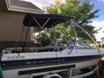
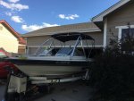
Capri 1950 Resto and Modernization

Baylinerchuck

Commander
Joined
Jul 29, 2016
Messages
2,726
I guess I’m pretty late to the party here, but things are really looking good with this boat. I have to say, I totally agree with not ripping everything out if you’ve done due diligence to ensure nothing else is wet. Just reading through the posts it appears you have. Believe me, I would not have ripped everything apart in my Chaparral if I didn’t need to. I would have reinforced nearly every joint where the wood met the hull, as boat manufacturers for the most part are pathetic at water proofing wood. We have way more attention to the details and time than a manufacturer. I am glad I did a full restoration though.

I hope I’m not going back too far, but did you put foam back under the deck? Judging from your in depth analysis and engineering calculations in previous posts, I assume you know how much structure and rigidity is added to the hull with foam. In boats with two stringers it’s paramount. Stringers, foam, and the deck all work together as one structure.

You were talking about the stringers being 3/4” plywood and how they are pretty worthless structurally. I’m not 100% convinced those calculations are correct, though I can’t really argue it, as I have no evidence. I’ve never really seen plywood deflect the way your calculations show. Two things I might point out in the discussion is that the plywood is a core, and way more rigid than dimensional lumber. Once the plywood is properly bedded and fiberglassed you have enormously increased that rigidity and I would be curious in what those calculations are. Also, most hulls are a compound design flattening significantly aft, thus the pressure is applied more upward from the bottom instead of from the sides in the bow.

CSM is good for waterproofing decks and wood structure but provides little in the way of strength. Most folks doing restorations here use 1708 for tabbing or covering stringers. The beauty in 1708 is that you have CSM which provides excellent adhesion when using polyester resins, stitched to biaxial mat which provides all the strength in a layup.

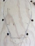
I love how you made your pattern for the deck. I’ll be using that idea in the future. Nice!!!!
 

Capriupgrade

Seaman Apprentice
Joined
Jan 24, 2019
Messages
33
Thanks for the feedback BaylinerChuck!
Ah, yes, foam...I absolutely agree that foam adds tons of strength and will reduce sound transfer. It will be going in maybe this weekend or next. I have about 4 cubic feet of 4lb foam that will go in the rear. And I probably have another 2-3 that will go in the boxes under the consoles. I took out probably 8 cubic feet. So this will get me close to original. I will probably put some foam or pool noodles under the gunwhales to take me back up to the full 2000 lb positive buoyancy of the original.

In regards to the plywood stringer, you are probably right, this is a simplified calculation based solely on the the moment of inertia of a 1x6" rectangle (10.4 in^4) and the Young's modulus (1500 ksi) for plywood. In reality, a free standing beam 12' long would probably rotate and buckle long before you could apply the load. By the numbers, Oak has similar characteristics as plywood (1595 ksi young's). Imagine applying a point load of 200 pounds in the middle of a 1x6" oak beam 12' long - it would bend 3/4 of an inch. Same as plywood, by the numbers.

point load.jpeg
Now, you are absolutely correct - once you encapsulate the plywood, the strength increases substantially. The back-of-the-envelope way to calculate the increase in strength is by using the Equivalent Area method - where you simply transform the thickness of materials based on their ratios of modulus. For this case:
The modulus of Glass Fiber Reinforced Polymer (gFRP) is 5,100 - 7,400 ksi.
The modulus of Plywood is 1,190 - 1,490 ksi.
Taking the upper ranges and finding the ratio = 7,400/1,490 = 4.96 = 5
So, we transform the thickness of the fiberglass by a factor of 5. Assume an original thickness of 1/8", this gives us a new thickness of 5/8"
Add it all together - 5/8" + 3/4" + 5/8" = 2"
So, the theoretical strength of an encapsulated 3/4"x6" stringer is equivalent to a 2x6 plywood stringer. Not to shabby! And you are right, I was looking at my hull this morning and it definitely has regions that become nearly horizontal at each chine, towards the stern. I assume these are the planing surfaces of the hull? So, my "triangle" model is definitely an over simplification for this type of hull. However, I am still confident my splicing and reinforcing has maintained/restored the integrity of the stringer.
In regard to CSM versus 1708 - I have gone back and forth between the two and I am leaning towards just CSM. This is because the original construction only used cloth on the final layer of the hull and nowhere else. I can tell when sanding through layers - cloth has a distinctive pattern that is visible when sanding through it. Everywhere else in the boat they used a chopper gun. So, why do I need the additional strength of 1708 when the original construction didn't use it and I didn't find any related structural issues? That's my current thought process...I may add some strategic bi-axial mat, depending on people's thoughts on the matter.

Thanks! This pattern method has save me a bunch of time and fitment headaches on this project!
 

Capriupgrade

Seaman Apprentice
Joined
Jan 24, 2019
Messages
33
One pet peeve for me on boats is all the places spiders can live. I know we can't get rid of them all, but I want to reduce spider places in areas commonly accessed. Because I want a 1.5" lip/flange on the tops of all the seat boxes for esthetic and strength reasons, this means the top lip of all the seat boxes are spider-prone.

IMG_7784.JPG
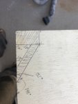
Here is my layout of the lip on the top of the seat boxes. The lip 3/4" ply, 1.25" wide. The diagonal corner cap is 3/8" ply. This should cap the spider areas under the lip and make a nice smooth transition for wrapping everything in fiberglass.
IMG_7797.JPG
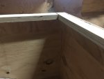
And this is how they look installed. It is somewhat difficult to see because the diagonal piece blends in with the verticle pieces, but they are there! I promise!

IMG_7798.JPG
Here is another view. This is also a good photo of the back seat pillars that I promised in my post yesterday. I am hoping all this extra work will end up with a less "plywood built" look to this boat. That's my hope at least. All the top edges will get a 1/2" or 1/4" radius to help blend everything.
 

Capriupgrade

Seaman Apprentice
Joined
Jan 24, 2019
Messages
33
Alright, let's talk about fillets, but not the edible kinds!

I want smooth transitions between the deck and the seat boxes. The traditional method is the use resin PB and spread it into the corners with a tongue depressor. This is fine and all, but the PB, in my opinion, has very little strength properties in the application and is truly a filler of convenience, which adds unnecessary weight and cost. I will use PB to finish everything else out in the end, but I want to start with a wood fillet in the corners to reduce the amount of PB I need to use. The wood will provide the same function as the PB - in that it will "fill" the corner and support the CSM, but provide a more controlled radius than I can achieve with PB alone.
IMG_7881.JPG
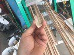
Here are the fillet pieces I made. I first tried making them out of 3/8" plywood and that was a bad bad bad idea!
First of all, my table saw is a 5hp 3 phase right tilt delta and it will throw things with a vengeance. Because the blade tilts into the the fence, the 45 degree corners I cut off the strips would get launched out of the saw anytime it reached a void. I used a variety of feather boards and push stick to keep my fingers, but it was not fun. Then, when I tried routing the radius in the pieces, there was nothing I could do to prevent the bit from chewing up the edges. You can see them in the right of the photo above - they looked terrible and where unworkable. Instead, I ripped a 4' 2x4 into 3/8" strips and was able to get like a dozen pieces out of it.
IMG_7880.JPG
Here is my 10 minute router setup for making the radius's. Just feed the strips with the face against the 2x4 cut at a 45 and push them through. Seemed to work pretty well on the strips from the 2x4. not so much on the plywood strips! lol.
IMG_7931.JPGIMG_7932.JPG
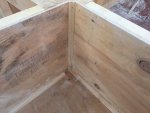
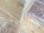
Here they are installed in a few places. I glued them with PL and then stapled them. The PL glue made a terrible mess and I will have to go back and do some touch up sanding. But overall the fillets look really good throughout the boat, and I think once I have everything fiberglass and gel coated, they will really blend the surfaces together. Oh, and that is a drain hole in the corner in that first photo, in case you are wondering. It allows deck water to drain through the seat box and into the bilge. I didn't want to do under deck drains as that introduces a potential point of failure for water under the deck.
 

Attachments

  • IMG_7875.JPG
    IMG_7875.JPG
    1.6 MB · Views: 5
  • IMG_7877.JPG
    IMG_7877.JPG
    1.2 MB · Views: 5

Capriupgrade

Seaman Apprentice
Joined
Jan 24, 2019
Messages
33
Okay, almost caught up to present!

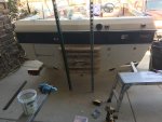
Last weekend, I mocked up the wake board tower. Starting to look like a boat again!
IMG_7884.JPG
IMG_7886.JPG
I couldn't really find any guidance for where to locate the tower, so I looked at a bunch of photos and determined most start their front mount around the front of the window. Therefore, that's what I did. The back position was chosen to allow the Bimini to go over the tower - this meant 60" behind the front mount, giving me a height of ~7' above the deck.
Unfortunately, there were no surfaces flat enough to bear the entire diameter of the mounting posts. So I chose to mount them in a concave corner. I will later machine some HDPE or delrin disks to fill in the corner so that I get good load transfer. ont he inside of the hull, I will add reinforcing to level out the corner and allow good contact area with the backing plate.

If anyone sees anything wrong with this or has some better guidance, I have only drilled the holes so far. So, I can easily patch the holes and move it if I need to. The rope mount is roughly centered over the seat backs of the captain and passenger.
 

Capriupgrade

Seaman Apprentice
Joined
Jan 24, 2019
Messages
33
Alright, I think I am finally caught up to present!

Yesterday and today I got the bulk of sanding done and started looking at getting the transom ready for bonding. The sanding was terrible, as expected, so no point talking about that much (I'll post some about it at the end of this post). However, for the transom, I need some opinions.
Click image for larger version  Name:	IMG_7936.JPG Views:	1 Size:	1.39 MB ID:	10794343
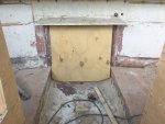
Here is the new piece I made roughly propped where it needs to go. I used 2 pieces of 3/4" ply bonded with a layer of 1.5 oz CSM. total thickness is ~ 1.5". existing hull is 0.375-0.5" thick, so I should be pretty close to target thickness when everything is bonded and fiber-glassed. if you are wondering about the bottom corner, It was 2 piece like this originally, so I will cut the last bit I need out of the scrap from the hole for the drive.
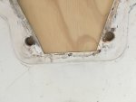
image_319933.jpg
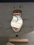
Now, here is where things get challenging. As you can see in the photo, the lower two drive mounting holes are very close to the edge of the hole for the drive. I am concerned they are too close and may have led to the demise of the old transom. My original plan was to just use the old hole as the template. But I am thinking I should either:
A) Find a good template print/PDF for an Alpha II drive
B) Use the drive I have on hand, and create a new template from it by using lots of craft paper, cardboard, and glue.
Thoughts?

Here is another question - Do people just drill out the mounting holes through the wood and slap the drive on with maybe some 3M sealant in the holes? Or do people do some sort of water proofing on the holes? Like, I was thinking, over sizing the holes in the wood, filling them with PB, and then re-drilling them the correct size - giving me a "Sleeve" of fiberglass in each hole. I feel like the latter method would be better, but is it overkill?
Click image for larger version  Name:	IMG_7934.JPG Views:	1 Size:	1.18 MB ID:	10794345
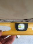
Here is another problem - the bottom 4 inches or so of the transom has this nice gap. Its just under 1/8 of an inch at its worst. Everywhere else is nice and flat across 24". If I recall correctly, mercruiser allows this much out of parallelism so long as the thickness is right. This was also how it looked before I gutted the transom. So, clearly bayliner thought it was acceptable. Will this be an issue? Or should I try to build it out? I am going to use a pretty heavy duty clamping setup (lots of 2x4s), so I am thinking I might be able to pull some of this out when I bond the new wood in.

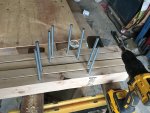
For clamping, I am going to use lots of 2x4s across the transom and threaded rod going through to matching 2x4s on the other side. The trick I am going use is I will put spacers between the 2x4s, inside the transom hole, that will prevent over-clamping and distortion. I will assume I want a 1/16-1/8" gap for PB, so I will set my spacers at ~2.05". This should, theoretically, help me maintain even thickness throughout. I will also probably put a few 2x4s over the main clamping 2x4s to keep them in the same plane as each other.

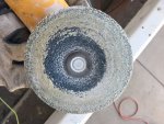
About the sanding - yeah, I should have done that first, before I framed in the boxes. It was terrible. The worst part I am finding is all that stupid carpet glue! It gums up sanding disks in no time!
Click image for larger version  Name:	IMG_7908.JPG Views:	1 Size:	1.93 MB ID:	10794346
At this point, I switched to a wire wheel before hitting it with sanding disks. That was slightly more effective...

I made it through most of it. But some of it I just can't get out without sanding away too much good fiberglass (because it has filled in the dips in the original fiberglass roving mat). In many areas of the hull, I just want to replace the carpet with gel coat. I don't want to grind too much fiberglass away as I will be reducing hull strength, and I wasn't planning on putting any fiberglass back. Does anyone know if polyester gel coat will stick okay to areas slightly contaminated with old carpet glue? I got most of it, but there is still a little...
 

Baylinerchuck

Commander
Joined
Jul 29, 2016
Messages
2,726
Awesome calculations on those stringers and fiberglass. I tried to follow along, but I’m just not that smart, lol. I rely mostly on the school of common sense....

I, like you, did not see the sense in plain old PB. It’s a great glue when clamping two substrates together, but that’s about it. I tried using it as a filler early on, but it cracked in some fillets. I started putting 1/4” chopped strand fibers in it and bang......super strong and not much added weight. My Chaparral had all those tiny strips of wood in it, and they were all rotten. I pulled all the wood out and replaced it with “hairy peanut butter”. All my fillets are hairy peanut butter. It does take a few minutes to knock the burrs down with a grinder before fiberglassing, but the strength and water proofing added is well worth it IMO.

I would use the 1708 for tabbing and glassing in the transom. I like the added bulk and strength. Most manufacturers used roving and chop guns. They left a lot of starved fibers and pooled resin. CSM is great for water proofing, biax for strength.

Mercruiser wants to see no more than + or - 1/16” of imperfection in the mounting surface of the drive. I was around 1/8” to 3/16” on my Chap. I decided to fair the area around the keyhole and gel coat. It turned out perfect.

Filling mounting holes with hairy PB and redrilling is definitely the preferred method. Whatever you can do to keep water from touching wood is well worth the effort.

Gelcoat needs a clean surface to stick. Spend the time getting all the glue off. It sucks getting that glue off. Once you wire wheel off everything visible, clean the surface with MEK. Prior to gel coating use MEK to clean. It will lightly soften the surface of the fiberglass and help the gel bond.

Looking good!!!
 

Capriupgrade

Seaman Apprentice
Joined
Jan 24, 2019
Messages
33
School of Common sense is sometimes the best rule of thumb...or at least keeps you from over complicating things!

Nice! I'll have to try the hairy PB fillets for the insides of all the seat boxes. I have used it in a few other places and it seems to be quite sturdy, so it sounds like a good and fast way to finish lower visibility corners to me!.

Yeah, I am thinking of ordering some 1708. My plan was to use CSM everywhere because the vendor used a chopper gun on everything. But, considering the transom is the most important structural component I am replacing, adding a layer of 1708 will add a little more assurance that this repair will hold up. Guess I'll have to place ANOTHER UScomposites order...lol.

Yup...I unfortunately found that mercruiser spec the other night. Which means I will have to fix it somehow. I also discovered that the problem is actually worse than I original thought - for pretty much the entire keyhole, the outside of the hull tapers inward about 1/16 to 1/8th of an inch, starting about 2" outward from the keyhole. I am speculating this is because the transom has been rotten for a long time and the force of the out drive pushing the boat around has cause the fiberglass to develop a "memory" of the inward force.
I am working on a potential "fix" for it without faring or grinding, hopefully it works. The fiberglass is flexible enough that I am thinking I can clamp 2x4s to the outside of the hull to pull it flat, then glue the 2x4s to the hull with resin so that I can remove the clamps and hopefully it stays. I then bond the transom to the hull and use the glued 2x4s as the outside half of my clamping jig while the transom PB sets up. Best case it holds and pulls most of it out. Worst case, it doesn't work and I end up faring and sanding anyways. It's such a small distance that I need to correct, I think this will work. If it was any worse, I wouldn't bother. We shall see though...
Dang! That's what I was figuring for the carpet glue...I was just hoping someone could tell me it was polyurethane and gel coat will stick. Fortunately, most of the worst is in areas under the gunwhales that will be covered with coaming panels and probably wont get much gel coat, if any. The rest I think I am going to try chemicals to remove as I don't want to remove any more fiberglass from the hull. I hope acetone and adhesive remover works!
Thanks for the advice!
 

Capriupgrade

Seaman Apprentice
Joined
Jan 24, 2019
Messages
33
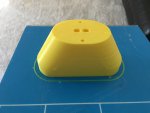
So, It has been a busy week at work, so not as much progress as I would have liked. But, I did make a little progress on a transom jig. As everyone probably knows, for the Alpha drive, the steering linkage requires diagonal relief holes drilled in the top corners of the keyhole. I am not sure how most people do it without a jig, but I decided to design and 3D print one.

When I took apart the transom, I saved the wood around the keyhole so that I could measure the diagonal hole diameter and angle. but of course, when I needed it, I couldn't find it. So, I searched the interwebs and found the detail I needed.
Trasome template diag hole detail.jpg
60 degrees. That's what I needed. So, I drew up a model of a jig to drill the 1/4" hole saw guide hole in the transom. It is based on the holes 4 inches apart, edged to edge, as they exit the hull. The hole saw should be 1.75", per mercruiser. It is also based on a fiberglass thickness of 1/2" so that when you screw it to the transom wood panel, the holes end up in the right place.
IMG_7944.JPG
Took 9 hours to print.
IMG_7945.JPG
Screwed it to a test 2x4 and gave it a whirl.

IMG_7948.JPG
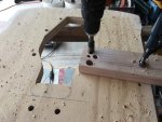
Worked pretty well. I did find out that the hole saw bottomed out halfway through the cut, so I tried finishing it from the other side. This doesn't work very well as the hole from the backside didn't line up and left an unsightly ridge where they connected. When I do this for real, I'll just stop halfway and chip out the plug, then proceed.

If anyone wants this jig, I can post the STL online somewhere and you can print it yourself. You know, I used to think 3D printing was just a novelty and had no place in shop as I can make parts far more superior on my mill or lathe. But, I am finding it more and more helpful due to it's ease of use, rapid prototyping capability, and decent accuracy (~0.005"). It is perfect for things like this - single/low use jigs or fixtures that don't take a lot of effort to make. Just draw up what you want while watching evening TV and then hit "Print". Wake up in the morning and your part is done! almost like magic!
 

Capriupgrade

Seaman Apprentice
Joined
Jan 24, 2019
Messages
33
So, I made a little progress on the transom...

In the last post, I described how I was thinking of "correcting" some slight inward bowing of the transom glass around the keyhole. Because the inward bow was less than 1/8th of an inch (closer to 1/16 really), I figured I could persuade it back out by applying some 2x4s, some resin, and a little force via a few clamps.
IMG_7973.JPGIMG_7980.JPG

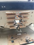
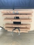
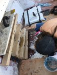
I started with six 24" 2x4s that I trued up both sides on the table saw so that they were nice and straight, and are all the same height. I then pre-drilled all the holes that will be used later to clamp the new transom. Then, I applied a liberal coat of resin to the 2x4s and clamped them to the transom. It took two stages as the second from the bottom had to wait until the first from the bottom was bonded, in order to use the clamps.
So far, I am very happy how it turned out. it looks to have pulled the transom perfectly flat in all planes (up/down, left/right, diagonal) with very little effort. Maybe ~20 ft/lbs max of clamping pressure to bring the transom glass to the 2x4s.
In theory, the new transom wood will then hold the hull flat while it is glassed in. I didn't clean the hull very well, so the 2x4s should be able to be knocked off easily with a hammer and then the resin sanded off down to the old gel coat (I will be re-gel coating the transom anyways). Hopefully it holds true and flat. Even if this doesn't work, worst case is I will have do some manual leveling and faring on the outside of the hull. So it is worth a try in my mind.

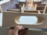
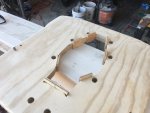
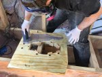
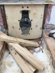
While I was waiting for the first five 2x4s to cure to the hull, I cut out the keyhole in the new transom wood.
IMG_7974.JPG
As I discussed earlier, I was concerned that the lower two holes were too close to the edge, so by looking at the clearance on the drive, I figured I could move the cut inward about 3/8" to give myself some space. If it is too tight, I can always remove material. Adding material back is much more difficult!
IMG_7977.JPG
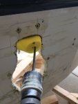
After I cut the keyhole out, I enlarged the bolt holes to 13/16" to allow me to fill them with PB and then re-drill to 9/16 - giving me a good seal on the holes. I will drill out the steering linkage clearance in place as that will be easier.

IMG_7979.JPG
Also while I was waiting for the first five 2x4s to cure, I prepped the inside clamping 2x4s. So, at this point, I have everything prepped for installing the new transom wood. I just now need a solid block of 2-3 hours to wrap this up!
 

Capriupgrade

Seaman Apprentice
Joined
Jan 24, 2019
Messages
33
Thanks 88 Capri!

Baylinerchuck - yeah! it seemed to work out great! Only downside is it made two small cracks in the gel coat, but just around the bottom of the keyhole where I will be grinding down anyways to blend in the CSM I will wrap the keyhole edge. So, totally worth the extra pre-work IMO!
 

Capriupgrade

Seaman Apprentice
Joined
Jan 24, 2019
Messages
33
Sorry I haven't posted an update lately! Work has been following me home the last week, which is cutting into my iboats time!

So I took the plunge and installed the transom last week. Here is how it went.
IMG_7996.JPG
I started by prepping the transom wood with 2.00" spacers inside the keyhole. They are exactly 2.00" and hot melt glued to the keyhole to line up with each clamping 2x4. The theory here is the spacers will bottom out on the 2x4s and ensure that I get uniform clamping thickness throughout the keyhole.
IMG_7998.JPG
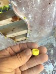
Next, I 3D printed some hole plugs 9/16" OD, 3/8" ID, and 1/2" tall. Because I am using the existing holes in the hull as my guide holes for re-drilling the transom, I didn't want them getting filled up with PB during the transom wood installation and getting off-center. These plugs allow the 3/8" threaded rod to be perfectly centered in the existing 9/16" hole. Afterward, I can use a step drill to drill the plugs back out to 9/16". I also coated them with some PVA, but I doubt that will prevent them from getting bonded into the hole.

I then calculated how much PB I would need. I assumed I needed a 1/4" layer of PB to ensure adequate coverage and plenty of squeeze out. This gave me ~2 qts required. Accounting for the material not needed for the keyhole, I figure 48oz would cover me. I pre-mixed two 24oz contains of hairy PB without MEKP. Then, once everything was staged and ready to go, I added MEKP to the first container and was off to the races!
IMG_8001.JPG
I tried using a notched trowel as I figured that would give me the best coverage and would allow it to spread out well when it was compressed. It worked OK, but hairy PB sure doesn't spread like thin-set or mortar! lol

This is a video of the frantic rush to get the transom in place and the clamping 2x4s positioned.

This video is of the clamping action and the squeeze-out of excess PB. I had PB squeezing out over the entire perimeter and the interior of the keyhole. I was able to reclaim probably 15 or so ounces from the squeeze out, which I used to fillet the edges. This was exactly what I wanted as it tells me that I shouldn't have any starved or hollow spots between the hull and wood. I figured wasting a bunch to squeeze out was better than not having enough in there! None actually went to waste though, which was good.
IMG_8024.JPG
The admiral was on squeeze-out recovery and fillet duty.

IMG_8026.JPG
before I started tightening any of the threaded rods, all of the 2x4s were perfectly in the same plane from top to bottom. After I tightened everything down, the bottom 2x4 was pulling inwards every so slightly. I grab some uni strut from my steel pile and screwed them to every 2x4 - giving the bottom 2x4 no choice by to comply with my demands.
IMG_8044.JPG
I let it cure overnight and then disassembled the setup the next morning. A swift tap with the dead-blow knocked each 2x4 off the hull. It is a bit difficult to tell with all the resin on the hull, but it appears to have stayed perfectly flat in all of the planes. So, that is exciting! Ill know for sure when I knock down the residue with the sander.
IMG_8045.JPGIMG_8047.JPG
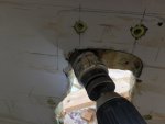
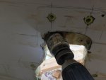
I then affixed my jig and drilled out the two holes.
IMG_8049.JPG
The holes came out perfect! The top cut connecting the holes, not so much...but that is how it originally was. I'll blend it some with the sander when I tackle the rest of the gelcoat that needs to be removed were the tabbing will go. That's it so for. This weekend will hopefully bring some tabbing of the transom and deck!
 

Attachments

  • IMG_8047.JPG
    IMG_8047.JPG
    570.3 KB · Views: 2
Top