1996 Four Winns Sundowner with 5.0 Cobra engine and drive

Lou C

Supreme Mariner
Joined
Nov 10, 2002
Messages
12,069
Take a pic of your dipstick so we can see
about cranking, I did a compression test last fall with all the plugs out, the ignition disabled, & throttle wide open and I don't think it varied in speed.
 

Scott Danforth

Grumpy Vintage Moderator still playing with boats
Staff member
Joined
Jul 23, 2011
Messages
47,950
the top of the hatched area should be the full mark. (about 3.5" below the pan rail)
 

Lpgc

Petty Officer 2nd Class
Joined
Jun 17, 2023
Messages
178
I'll take a pic of the dipstick tomorrow.

I have a theory why the dipstick reads over filled - The dipstick tube enters the oil pan from the side near the bottom of the sump. A dipstick going sideways into an oil pan could only show no oil or some oil but couldn't tell you how much oil was in, so I expect the dipstick doesn't go all the way into the sump but stops part way in the long dipstick tube... The dipstick tube will be supposed to rise at an angle (diagonal) as it comes up from the drain/sump plug level past the outside rear of the sump, the dipstick will measure level in the tube (not in the sump) but that's OK because it will find it's own level (the level in the tube will be same as level in the sump)... except I fitted the dipstick tube so it passes the rear of the sump horizontally instead of at the angle/diagonally, so now when the dipstick gets into what should be a diagonal section it's already horizontal and will only show no oil or some oil. Does this sound correct?

If that is correct then I'd need to slacken the dipstick tube from the sump and reposition it so the end of the dipstick tube is diagonal, but should I try to do that while the engine still has oil or pump all the oil out first? Maybe I should try to slacken it a little and see if I can reposition it without losing much oil, have a bowl and rags under it to catch any spillage...?

Pumping it out would be a no brainer but I found something else out today, I didn't know that the dipstick tube is designed with a garden hose type fitting to connect an oil pump to, previously I thought the idea was to put a narrow pipe through the dipstick tube and use a pump to pump it out. Just bought a pump to help pump petrol out of the fuel tank and hoped to use the same pump when I needed to pump oil of the engine but maybe I should buy a pump that connects to the garden hose type fitting on the dipstick tube now (Quicksilver?)...
 

Lpgc

Petty Officer 2nd Class
Joined
Jun 17, 2023
Messages
178
Take a pic of your dipstick so we can see
about cranking, I did a compression test last fall with all the plugs out, the ignition disabled, & throttle wide open and I don't think it varied in speed.

Thanks. I mean with the plugs in. With the plugs out I expect there'd be a constant pitch sound when cranking the engine but with the plugs in the rise and fall in pitch (and engine speed, the familiar whir whir sound) is due to the speed slowing every 90degrees of rotation when a cylinder reaches near peak compression... If there's an equal whir whir sound (up and down in pitch) but every 2nd rotation of the engine there isn't a drop in pitch at one of those 90 degree positions it could point to lack of compression on a cylinder, which is one of my concerns.
 

Lpgc

Petty Officer 2nd Class
Joined
Jun 17, 2023
Messages
178
Got the engine running :cool: Seems OK.


Pics of the dipstick and tube

20240517_165238.jpg 20240517_165112.jpg

20240517_165159.jpg

Used the multimeter to check oil pressure (resistance of the new sender unit), reads 240Ohms with the engine off and around 130Ohms with the engine running which I believe points to somewhere around 45psi? Also used it to test charging voltage, it brought the battery up to 14.8V which seems a bit high? I might make the mod discussed earlier in which the alternator sense wire is connected closer to the battery.

The starboard side manifold, riser and metal down pipe was getting hot but soon cooled down after switching off the engine... as though some water was flowing through it but not enough to keep it cool. The port side components stayed cool throughout. Maybe just down to not enough volume of water coming from the hose pipe, or could I have put too much sealant on the gasket between the riser and manifold?

Problem I've got now is that it is hit and miss whether turning the key to crank the engine will crank the engine, some sort of electrical problem. A previous owner had some sort of makeshift immobiliser fitted, it won't crank unless the cabin lights switch is on, seems the previous owner had a marina set it up like that because I have a video of a guy from a marina showing the owner how to start it (presumably after the marina fitted the immobiliser). I intend on removing the immobiliser and cleaning up some untidy wiring around the helm. One time it refused to crank it did crank after I pulled on some of that wiring. I can always start it by turning the ignition on and jumping the start solenoid on the engine.
 

Attachments

  • 20240517_165157.jpg
    20240517_165157.jpg
    1.4 MB · Views: 2
  • 20240517_165047.jpg
    20240517_165047.jpg
    1.7 MB · Views: 1
Last edited:

Lou C

Supreme Mariner
Joined
Nov 10, 2002
Messages
12,069
Engine sounds good! No weird noises! Just a lil water leak just tighten clamp. Saw dipstick, you keep it in the safe area between the arrows. These dipstick tubes can give odd readings because the oil level in the tube has to equalize to read accurately. Best is to pull the stick out & wait a few min to allow the level to equalize & then check it.
 

Lpgc

Petty Officer 2nd Class
Joined
Jun 17, 2023
Messages
178
Engine sounds good! No weird noises! Just a lil water leak just tighten clamp. Saw dipstick, you keep it in the safe area between the arrows. These dipstick tubes can give odd readings because the oil level in the tube has to equalize to read accurately. Best is to pull the stick out & wait a few min to allow the level to equalize & then check it.
Thanks Lou.

Yeah I think the problem with the reading on the dipstick will be because (as said above) I didn't fit the dipstick tube at the correct angle. I think I'll try to slacken the tube as it enters the oil sump and change the angle so the tube rises quickly away from the sump fitting, try to do that without losing much oil into the bilge.

I put some PAS fluid in the pump and moved the steering from lock to lock with the engine running, PAS works OK, I was surprised that there was no foaming of the fluid like I'd usually expect after emptying and refilling a PAS system. Maybe there'll be some more air come out when it's working under load (when the boat is in the water and the PAS has to move the leg under load). I'll take some PAS fluid with me first time I use the boat.

I made a hosepipe to thermostat housing adapter from a flexible but hard plastic funnel tube, just the best thing I could think of quickly to use. The wide end of the tube fits on to the stat housing but is too wide to make a watertight seal even though it's jubilee clipped on and I put tape around the stat housing raw water input, the leak is coming from the connection between the stat housing and hose... I thought it'd suffice for just test running the engine. As advised, I did prime the engine with water through the bottom wp hose up to the stat level and pre-fill the manifold cooling channels before fitting the stat housing and running the engine.

I think the old plug leads can stay on the engine for the first time I use the boat, they seem OK, Not sure whether to fit the new dizzy cap and rotor arm. I will check ignition timing with the strobe light before I use the boat. When putting the engine back together I checked the timing pointer was in the correct position by finding true TDC using a magnetic dial gauge, it was spot on in the correct position.
 
Last edited:

Lou C

Supreme Mariner
Joined
Nov 10, 2002
Messages
12,069
👍
I had a 1970 Ford Torino with the same engine many years ago. Ford small block V8s were very well regarded. Simple tough old school construction. Mine had a Motorcraft (Ford) 2 bbl carb, C4 auto transmission and Ford 9” rear end.
 

Lpgc

Petty Officer 2nd Class
Joined
Jun 17, 2023
Messages
178
Not done much on the boat today.

I did repostion the dipstick tube so it's routed a little higher, had to disconnect the starter motor power lead connections to make enough space to get access. Then I took @Scott Danforth advice from another thread...
Measure the tube to the point 3.5" below the pan rail

Measure the dipstick an put a mark that distance from the handle end
and found out the dipstick (which is on the port side but the tube routes under the oil pan to the starboard side) only goes down part way of the port side... but the level indication will still be influenced by the height of the tube on the port side. Using Scott's method I found my oil level seems to be around 1 inch below the oil pan lip. Is that OK or is it overfilled?

Tested the fuel level sender that arrived recently using the multimeter. It's a reed switch design with vertical acting float (as opposed type that has the float at the end of a flat arm), I think I prefer this type. The multimeter showed it gave 240Ohms at the bottom position and 33Ohms at the top position but there's quite a quick transition from 240 to around 150Ohms then it becomes more linear. I don't know the linearity of the standard sensors but I think this will give the kind of response I prefer from the fuel gauge being more accurate towards the empty end of the scale.

20240518_170957.jpg

Hopefully tomorrow I'll get time to do a bit more, if not it might be midweek before I get any more time, other work to do until the the middle of next week.
 

Scott Danforth

Grumpy Vintage Moderator still playing with boats
Staff member
Joined
Jul 23, 2011
Messages
47,950
on an SBC, you are over filled if you are 1" below the oil pan lip. that means the crank is splashing in the oil creating foam
 

Scott Danforth

Grumpy Vintage Moderator still playing with boats
Staff member
Joined
Jul 23, 2011
Messages
47,950
for an SBF. about 3.25" below the oil pan flange (had to google that as it has been a long time since I played with a ford)
 

Lpgc

Petty Officer 2nd Class
Joined
Jun 17, 2023
Messages
178
for an SBF. about 3.25" below the oil pan flange (had to google that as it has been a long time since I played with a ford)
Thanks for looking that up for me, useful info. It just occurred to me the oil should be a certain level below the flange regardless of the oil pan design to allow space to make sure the crank (which will go below flange level) clears the oil. Hang on though, if the oil is in the sump part of the oil pan it must be below the flat level of the oil pan so the crank turning should miss the oil in the sump anyway? I will drain some out but it shouldn't normally cause a problem unless G forces etc splash some oil out of the sump?
 

Lpgc

Petty Officer 2nd Class
Joined
Jun 17, 2023
Messages
178
I got a bit of time to work on the boat today, been messing with the dashboard instruments. To recap, this is the Four Winns car style instruments, the problem was all the dials seemed to move but all pointed to the wrong place. I removed the instrument cluster and using 2 small spoons (it's a method that I use on car instrumet clusters) tried to prise the orange needle off the voltmeter first, it seemed like it was going to break before the needle came off so I started disassembling the cluster hoping I'd find a way of adjusting where the needle pointed from the rear. It became clear I wasn't going to be able to remove/reposition the needle from the rear so I thought since it was already effectively broken (as in none of the needles pointed to the correct position) I had nothing to lose by trying a bit harder to prise the needles off using the spoons method. So far I have successfully fixed the voltmeter and trim gauge (verified by testing), and I've got the rev counter and oil pressure gaige both pointing to zero with the ignition on but I haven't tested the accuracy of those yet. The next thing I'll do is remove the new fuel sender from the tank and try to fix the fuel gauge (again using the spoons to reposition the needle), then the coolant temp gauge.

A few questions...
I noticed there is a number of engine cylinders selector (for the revcounter) on the back of the instrument cluster but it is marked only with 2, 4, and 6. My engine is an 8 cylinder, makes me wonder if someone fitted the wrong cluster or swapped the engine from a V6 to a V8. It is currently set to the 6 cylinder position. What is the 2 position for? I think if I set it to the 4 position I could buy/make electronics that fit between the coil and revounter feed and half the number of coil pulses sent to the revcounter, then the revcounter should work properly?
What is the spec of the coolant temp sensor (looking for an Ohms versus temperature table)? With that info I can disconnect the wiring from the engine coolant temp sensor to temporarily wire in resistors to check the gauge on the dash points to the correct position.

Instrument cluster removed but before I started adjusting the needles
20240520_121013.jpg

All the gauges are easily removed from the circuit board by unscrewing 3 nuts for each gauge. The metal housing will come off when the gauge is removed... But this doesn't help reposition the needles, to reposition the needles I didn't need to dismantle the cluster, just prise the needles off from the front.
20240520_125030.jpg
 

Attachments

  • 20240520_120934.jpg
    20240520_120934.jpg
    2.2 MB · Views: 3
  • 20240520_120945.jpg
    20240520_120945.jpg
    2 MB · Views: 3
  • 20240520_120952.jpg
    20240520_120952.jpg
    2.1 MB · Views: 2
  • 20240520_121005.jpg
    20240520_121005.jpg
    936.5 KB · Views: 2
  • 20240520_125015.jpg
    20240520_125015.jpg
    1.7 MB · Views: 1
  • 20240520_125023.jpg
    20240520_125023.jpg
    1.9 MB · Views: 4

Lpgc

Petty Officer 2nd Class
Joined
Jun 17, 2023
Messages
178
Adding to my last post...

Hopefully I fixed all the gauges in the car style instrument cluster. Tested them all with various electrical resistance to earth instead of connected to respective sender units and all readings responded as they should. The only gauge I haven't tested is the rev counter.

Gauges now with ignition on. Not properly fitted yet, just resting in place. But while I had all this removed I did polish up the clear perspex.

20240520_192742.jpg

This is the control on the back of the instrument panel that switches between different number of engine cylinders for different applications. I wonder if the number at the bottom is supposed to be an 8 and I should move the pointer to the 8?

20240520_192322.jpg

Work in progress, in this pic I connected some resistors between earth and the coolant temp sensor wire. I did the same for oil pressure. For fuel gauge I just removed the fuel level sender and manually moved the float. For tilt/trim I had my friend move the drive leg bevel up and down. For the revcounter I just set it to read 0 rpm with ignition on engine not running. Seems all the gauges are working fairly accurately now :)

20240520_160712.jpg

Info I found about oil pressure / temperature / etc versus sender resistance

20240520_152207.jpg

That saved some money because I do want working gauges. The instrument console was riveted together, I driled the rivtes to dismanntle it. I may just use a couple of spots of superglue to help keep it together on final reassembly but it seems to hold together OK in the installed position without needing anything to secure it.

Begs the question why the needles were installed in the wrong position, I reckon it must have been removed before and someone didn't put the needles on correctly.
 

Attachments

  • 20240520_160714.jpg
    20240520_160714.jpg
    1.7 MB · Views: 1
  • 20240520_192251.jpg
    20240520_192251.jpg
    1.9 MB · Views: 2
  • 20240520_192324.jpg
    20240520_192324.jpg
    3.2 MB · Views: 2
  • 20240520_192528.jpg
    20240520_192528.jpg
    2.6 MB · Views: 2
  • 20240520_192755.jpg
    20240520_192755.jpg
    2.8 MB · Views: 1
Last edited:

Lpgc

Petty Officer 2nd Class
Joined
Jun 17, 2023
Messages
178
Been trying to fix some electrical gremlins.

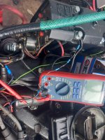
I still haven't got to the bottom of the 'immobilser' issue but I might have fixed that anyway. To recap a marina sent the previous owner a video showing how to start the engine... turn the ignition on, then flick the cockpit light switch on/off, then turn the key to start. Originally it wouldn't start unless that procedure was followed. I took some voltage readings today, 12.6V at the key switch with ignition off but dropping to around 10V at the key switch with ignition on and around 9.9V at the ignition coil. I wondered if there was a ballast resistor fitted somewhere and if it was wired up wrong so the key switch was powered through (said) ballast resistor, but I didn't find a ballast resistor. I did find a purple wire getting warm at a crimped joint near the engine bay circuit breakers and fixed that by cutting out the crimp and soldering wires together, but the main thing I found was that the ignition switch was wired through the dead man switch (which I should have guessed) and the dead man switch had around a 1.5V voltage dtop across it with the ignition on (when supplying the ignition coil). The voltage drop due to the dead man switch was enough to see that when the key was turned to the crank position the voltage fell too low to turn the starter motor solenoid on. I have bypassed the dead man switch and now it seems to crank and start on the key every attempt.

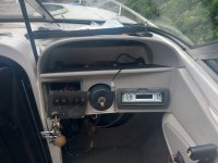
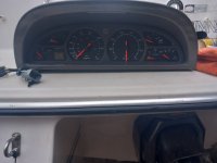
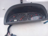
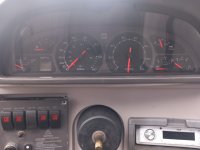
I had already calibrated the voltmeter on the instrument cluster to show battery voltage, I now realised I should calibrate it to show voltage at the key switch because after the (above) fix it was reading higher than actual voltage. I removed and refitted the needle of the voltmeter (again) and now it shows voltage at the ignition switch accurately.

The bilge blower and bilge pump were not working, that turned out to be just due to a bit of corrosion on the fuses and fuse panel / switch panel spade connectors. They are now working properly. The bilge pump did work in automatic mode (from float signal) even before I did this fix.

Removed the sub/bass speaker cabinet from the cabin. Heh, for the time being there is a 12" hole from the driver position (near drivers legs) through into the cabin where the speaker was fitted. I might get aorund to filling that hole with something but in the short term I'll just refit the 12" speaker in the hole.

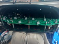
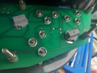
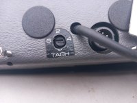
I set the number of cylinders selector on the rear of the instrument cluster to what I thought could be the 8 cylinder position but the revcounter still seems to be reading high (judging rpm by ear). I will attach a discrete digital revounter to check the accuracy of the instrument cluster revcounter.

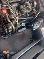
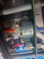
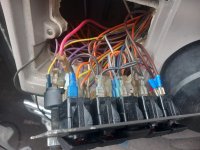
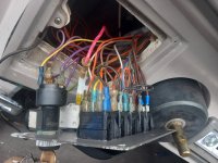
Pictures of poor crimped connection of the purple wire in the engine bay. After taking the pictured I removed the crimp and soldered the wire together.
20240521_155514.jpg 20240521_160605.jpg

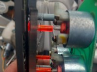
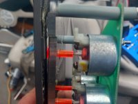
12V feed from engine bay (thick pink wire) goes through the discrete fuse holder, purple wire from discrete fuse holder goes to dead man switch, another purple wire comes back from the dead man switch to feed the key switch. After taking the pic I connected the pink wire directly to the key switch, bypassing the dead man switch.

20240521_124033.jpg
 

Attachments

  • 20240521_124018.jpg
    20240521_124018.jpg
    2.6 MB · Views: 0
  • 20240521_124022.jpg
    20240521_124022.jpg
    2.6 MB · Views: 1

Lpgc

Petty Officer 2nd Class
Joined
Jun 17, 2023
Messages
178
This is the control on the back of the instrument panel that switches between different number of engine cylinders for different applications. I wonder if the number at the bottom is supposed to be an 8 and I should move the pointer to the 8?

View attachment 398347
I doubt this instrument cluster would be fitted on a boat with a 2 cylinder engine, which made me wonder if the tach settings control points to number of ignition pulses per engine rotation in which case it should be set to 4 for the V8? I've set it to 4 now but haven't started the engine to test the tacho since.

Only done a little work on the boat today, changed the earth strap 4 battery number 2 because the cable smoked when I tried to start the engine from that battery. The cable was corroded.
 

Lou C

Supreme Mariner
Joined
Nov 10, 2002
Messages
12,069
Yep that car style instrument cluster I’ve never seen so it’s hard to say what setting is correct but it wouldn’t be hard with the engine running. Just hook up a tach/dwell meter to the engine & check it against the instrument panel tachometer or rev counter as you say…
Good catch on the corroded cable. The cables that came with my boat were junk & I replaced them about 15 years ago…used Ancor marine cables those last a long time because they are tinned….
 

Lpgc

Petty Officer 2nd Class
Joined
Jun 17, 2023
Messages
178
Had hoped to get a bit of time to work on the boat today but real work got in the way.

I'll be refitting the OMC Cobra (Volvo SX) drive leg soon. I bought the odd shaped water intake gasket that seals between the leg and transom swivel, the odd shaped gasket fits fine but it came in a pack with 2 O rings... Where do the O rings fit? I was wondering if they fit on the leg input shaft or between the leg and transom. Also, is there defnitely no gasket between the leg and the transom swivel? I think I've seen pictures of a gasket that seems to match the shape.

A little hand pump I bought to refill the SX leg with fresh 75/90 arrived today. Does the leg really need to be filled from the bottom hole or can it be filled from the middle hole?

Bought some oxalic acid powder to clean up some rust marks on the bathing platform and the 'tide mark' around the boat from when I last used it on the river. Is this the best stuff to remove the stains? Is a 10% concentration the right mix for both purposes? Heh when you can get acid delivered through the post lol... How dangerous is this stuff?
 
Last edited:
Top