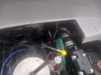
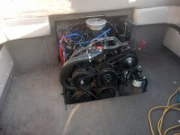
1996 Four Winns Sundowner with 5.0 Cobra engine and drive

Lpgc

Petty Officer 1st Class
Joined
Jun 17, 2023
Messages
262
Why not look on the EU Volvo Penta parts site and see if they sell a rebuild kit for your year, remember it is the same as a Volvo SX.

I looked all over the internet, made phone enquiries, etc, nowhere has a kit for the pump.

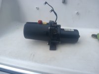
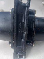
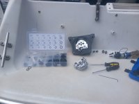
I bought a few sets of O rings, mostly metric but one imperial set. Today I removed the trim pump, stripped it and currently checking O rings and replacing any I think are suspect (if I've got suitable size in the kits), followed the stripdown steps taken by Michael Romer in a Youtube video which I've watched before. If I'd remembered (from watching it before) I would have bought more imperial than metric O ring sets, he links to an imperial set in the comments, I didn't remember if the O rings were going to be imperial or metric and guessed wrong.

20240529_133146.jpg 20240529_133201.jpg

20240529_152318.jpg
 
Last edited:

Lou C

Supreme Mariner
Joined
Nov 10, 2002
Messages
12,821
Great work, it is good for those who have not done this before to see what's involved. The pump given it's age looks very clean inside....
 

Lpgc

Petty Officer 1st Class
Joined
Jun 17, 2023
Messages
262
Great work, it is good for those who have not done this before to see what's involved. The pump given it's age looks very clean inside....
Thanks, I'm just copying Michael's method really so credit should go to him.

In my last post picture the 2 O rings outside the O ring box are one that I took off and same size as one I replaced it with. The one I took off had very slight scuffing in an area on it's outer edge and (if the one I put on is correct size) had stretched, also definitely flatted on it's outer edge.

Been doing this outside just on the back of the boat but it's started raining so I packed everything up until the rain stops.

Used Michael's idea of packing holes with grease to get the 2 pistons (for want of a better term?) out of the holes they're flush with. Michael used a 7/16UNF tap, I have a 7/16UNF tap but mine is the type with 3 large slots down the side to channel swarf out and screwing my tap in just had grease filling the channels in the tap. Thought I'd got a 7/16UNF bolt but couldn't find one, then I remembered the threads on the bar that goes through the drive that the rams attach to has 7/16UNF thread, removed then nut from one side of the bar and screwed my pump assembly onto the bar, the grease did it's job and I got the 2 pistons out. I have since cleaned all the grease out but that's where I'm up to now with rebuilding the pump until the rain stops.

There was a very small amount of emulsion (hydraulic fluid mixed with water) in the pump, I don't know if that points to water entering via the rams or just condensation inside the pump but it really was only a very tiny amount that might equate to just a couple of drops of water if it hadn't mixed with the fluid.
 
Last edited:

Lpgc

Petty Officer 1st Class
Joined
Jun 17, 2023
Messages
262
At 9:45 into Michael's video (that I linked to above) he removes the expansion valve. There are 3 seals on the expansion valve one of which is white and differs from all the other seals because it's white and some kind of harder material. My white seal has a fairly neat looking 45 degree split through it, I need to know if that split is supposed to be there or not....
 

Lou C

Supreme Mariner
Joined
Nov 10, 2002
Messages
12,821
Michael’s done a ton of stuff including a transom rebuild. Quite a talented & skilled guy!
 

Lpgc

Petty Officer 1st Class
Joined
Jun 17, 2023
Messages
262
Michael’s done a ton of stuff including a transom rebuild. Quite a talented & skilled guy!
He certainly is, I enjoy watching his videos and have watched quite a few, they've proven useful for all sorts of things such as finding out where the ancillary brackets bolt on the engine (or rather water pump) which I found by watching a video of him change ancillary drive belts. The only things I would have like to have seen him cover in the video I linked to above were the white seal/O ring (split or not split) and there are 2 little valves with tiny little bird shot sized ball bearings inside them I wasn't sure which way were supposed to be fitted. Someone else asked him about the 2 little valves (in the YouTube comments) and he did reply with 'check the diagram' with a link to the diagram, I already had the diagram open and found which way the valves went. Still a great video with plenty useful tips.

I put the pump back together. last night but didn't have time to refil and test it. Filled it today, the motor ran but the leg didn't move. Disconnected the lines from the pump and ran it, still no fluid came out of the line holes on the pump. Removed the pump again, think I had the motor to pump adapter (same kind of thing as a 3/8 to 1/4 socket adapter but with straight slots instead of square holes) in the wrong gear.. Easily fixed by moving it to the other gear. Tested before refitting on the boat by connecting to a battery, fluid shot out of (respective) holes depending on which polarity I connected the battery. Refitted it on the boat, now it seems to be working :). I've left the leg half way up in around the same position from which it fell overnight under its own weight, so now I'll see if it falls again and if it does will rebuild the rams.
 
Last edited:

Lpgc

Petty Officer 1st Class
Joined
Jun 17, 2023
Messages
262
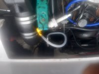
Used the same little pump I used for filling the leg with hypoid oil for filling the tilt/trim pump after thoroughly washing it out, same threads as the drive drain plug hole. Just had to keep disconnecting the tube from the pump to let the air pressure out. A lot less potential for making a mess than the method I used last time, think I used a small funnel with tube attached last time.

20240530_145710.jpg 20240530_173424.jpg

How should the trim gauge on the dash work (linearity - does the gauge move slower at one extreme of trim than at the other extreme)? I can't fully test mine at the moment because the skeg hits the ground before it's trimmed all the way down... But it doesn't look like it would go much further down even if it didn't hit the ground and when it's down in that position the gauge is only showing half way down. I'm hoping the gauge moves quicker near the full down position than near the full up position. Seems it'd make more sense for the gauge to move quicker around the down position because that's the position it will be in during use and where we need the gauge to be more accurate?
 
Last edited:

Horigan

Senior Chief Petty Officer
Joined
Jun 12, 2016
Messages
675
Once you're able to get the drive fully down, adjust (rotate) the sender until the gauge reads fully down. My gauge tends to show more movement near down than when trimmed up for trailering.
 

Lpgc

Petty Officer 1st Class
Joined
Jun 17, 2023
Messages
262
Once you're able to get the drive fully down, adjust (rotate) the sender until the gauge reads fully down. My gauge tends to show more movement near down than when trimmed up for trailering.
Thanks, I havent had a good look at the sender yet or researchd how to change/adjust it. I just see 2 wires disappearing into the rear transom stuff lol.

I did read somewhere that it's an engine out job if it needs changing?

Come to think of it, I think it will work. Before I fitted the drive I had a friend move the swivel housing (again I forget the correct term) on the outside of the transom that the drive bolts to, the gauge did move to the full down position when the drive was fully down... But will the rams retract enough in the full down position to move the swivel mount fully down?
 

Lpgc

Petty Officer 1st Class
Joined
Jun 17, 2023
Messages
262
I was undecided whether to refit the rear trim before testing the boat but decided to refit it. With the rear trim refitted it'll be OK for anyone to come with me when I first test the boat, without rear trm fitted it limits the number of seats and leaves spinning bits of engine exposed. Only partly refitted the rear trim today.

20240531_194137.jpg

Edit - Before refitting trim I test started the engine again then fitted the V belt for the raw water pump.
 
Last edited:

nnl1987

Seaman
Joined
Sep 20, 2016
Messages
52
Thanks, I havent had a good look at the sender yet or researchd how to change/adjust it. I just see 2 wires disappearing into the rear transom stuff lol.

I did read somewhere that it's an engine out job if it needs changing?

I just changed mine this spring. You will need to take off the stern drive to change it. You won't have to remove the engine to change it however you will curse the whole time you do it. You will be laying on top of the engine basically. Although it does look like you have more room to the left and right of the engine then my boat. Might be a bit easier.
 

Lpgc

Petty Officer 1st Class
Joined
Jun 17, 2023
Messages
262
I just changed mine this spring. You will need to take off the stern drive to change it. You won't have to remove the engine to change it however you will curse the whole time you do it. You will be laying on top of the engine basically. Although it does look like you have more room to the left and right of the engine then my boat. Might be a bit easier.
Thanks, I don't think there's a problem with the sender at the moment... I had a problem with the car style dash gauges, all the gauges were pointing to the wrong positions but I fixed that by just removing the dials from the needles and repositioning them. With the drive removed I had a friend move the transom swivel for the drive up and down and fixed the pointer for the trim gauge so it pointed to up when he moved the swivel fully up and down when he moved the swivel down and the gauge moved smoothly between points. It would be a shame if the sender did need changing now because I recently fitted the engine hehe. I can't move the drive fully down at the moment because the boat is on the trailer and the drive hits the ground before it is fully down, but the cavitation plate on the drive does seem fairly parallel with the bottom of the hull when the drive hits the ground and in that position the trim gauge on the dash shows half way, hence my questions.

What is the limiting factor for how far down the drive will trim, is it the rams reaching full in position or the transom swivel?
 

Lpgc

Petty Officer 1st Class
Joined
Jun 17, 2023
Messages
262
Today I refitted most of the interior trim.

Then did some gardening :-( The drive has some hawthorn trees alongside which are slow growing and OK but there's some sort of quick growing shoots that have been climbing up the hawthorn trees and hanging down to the point they reach my car windscreen. Twice a year I cut this stuff back and it's a pita, getting fed up of doing it, been researching what this stuff is and how to kill it, for now I've just been using the petrol powered brush cutter. Had to trim it back before using the boat because the boat is taller than the car.

Noticed a little patch of oil under the drive. Turned out I hadn't tightened the drive drain plug. It's not leaking now but I'll still need to top up the 75/90 before using the boat. I didn't fit a new drain plug seal, not even sure of the part number for it. Does anyone know if my 1995/6 OMC Cobra (but Volvo SX spec) drive uses an OMC spec drain plug or Volvo spec drain plug, or are they the same?

Took the cushions out of the cuddy, will give them a wash later this week. Seem to have a missing centre fill-in cushion so it won't make up into a bed... I might never sleep on the boat (or maybe I will) but I want the facility so might look into buying/making/having made a centre cushion. Are the entre cushions one piece or in multiple parts? Wondering where centre fill cushion(s) and support(s) are supposed to be stowed in the cuddy when not in use? 1995 Four Winns Sundowner 205.

Not much more to do on the boat before it'll be ready for a water test but I'm not happy with the electrics (or more specifically the fuse box) yet. None of the electrics were working when I flicked the switches (manual bilge pump, blower, front light, etc) until I removed and re-inserted fuses multiple times, they're working now but I'd only have to move the fuses a little for them not to work, could say the electrics are temprimental and I don't like temprimental electrics on cars or especially boats because it means unreliable, I want to get the fuses more reliable than that. Also need to tidy (and tie up) wiring under the steering wheel and around the fuse box and refit a panel cover / fire extinguisher mount that goes over the fuse box, don't like having wiring hanging down.

Not a priority but I want to address what I see as a design issue that probably sees the alternator overcharge on a lot of boats. My new and old alternator have a separated ignition-on (exciter) and voltage sensor connector but they are wired in parallel and both connect to the proverbial purple wire in the engine bay that is the ignition on wire. On my boat there was initially a big voltage drop (from battery voltage to voltage at the engine) on the purple wire, mostly due to a voltage drop across the dead-man switch (which I fixed by bypassing the dead man switch) but even with the dead man switch bypassed there is still a bit of voltage drop from battery voltage to purple wire voltage at the engine... I believe the alternator will overcharge because it gets its battery voltage reference from the purple wire which has a bit of voltage drop. I'm thinking of fitting a relay in the engine bay that will be switched by the purple wire and connect the alternator voltage reference to actual battery voltage instead of to purple wire voltage, on my boat that could mean connecting the switched circuit of the relay to the solenoid post on the engine. Heh before I realised the problems with my voltage drop on the purple wire (due to the dead man switch) I freshly charged a good battery, the engine started immediately, but I knew the alternator was working flat out due to the whine sound it made. I believe that if the alternator was sensing actual battery voltage (instead of purple wire voltage) it wouldn't have been charging so hard. No worries for the moment and a bit too much charge is better than too little charge but it is something I intend on addressing, I don't want the alternator to overcharge and boil away 2 good batteries or for the alternator to be working unnecessarily hard. There was only 9V at the purple wire at the engine (ignition on engine not running) with a freshly charged 12.6V battery before I fixed the dead man switch issue, that's a 3.6V voltage drop, but even after fixing the dead man switch issue there's still only 11.7 on the purple wire with ignition on engine not running with the battery at 12.6V, that's a 0.9V voltage drop. The 0.9V voltage drop will see the alternator want to charge the batteries to 15.5V instead of 14.6V, which seems a design flaw.
 
Last edited:

Lpgc

Petty Officer 1st Class
Joined
Jun 17, 2023
Messages
262
Hopefully taking the boat to the river tomorrow.

Still minor things to do such as tidying the drooping wires under the instrument cluster, secure some interior trim and change plastic bushes on the SX drive but all being well it should be in workable order tomorrow.
 

Lou C

Supreme Mariner
Joined
Nov 10, 2002
Messages
12,821
The issues with the fuse box (old fashioned glass fuses) I have had due to oxidation and salt air where my boat is moored. What I do is clean the contacts at the start of each season and spray with corrosion inhibitor. The over charging problem I also had. The solution I learned from ARCO marine which is a company that makes aftermarket alternators and starters. I bought one of their starters and the instructions said that due to resistance in the harness the alternator will sense a low voltage condition & over charge the batteries. ARCO’s instructions with the new alternator I bought advised disconnecting the sense wire at the alternator and tape it up in the harness. Then run a jumper wire from the sense terminal to the B+ connection on the alternator. The large B+ wire is connected to the starter solenoid which is also directly connected to the battery or battery switch common terminal. Re wiring it that way my charging voltage at the batteries dropped from 15.5V to 14.2V. So I’d try that.
My plan for the fuse box is to replace the old one with glass fuses with a modern Blue Seas 12 circuit fuse box,
 

Lou C

Supreme Mariner
Joined
Nov 10, 2002
Messages
12,821
PS an even better way to set up the alternator wiring which I might do in the future:
The alternator has a ground terminal; while it’s grounded to the engine corrosion & resistance can cause voltage drop. So an 8 gauge ground wire can be run from the ground terminal to the ground stud on the engine bell housing which is also where the battery negative cable connects.
Second, since optimal voltage sensing should be close as close to the battery as possible; the sense wire can be run from the S terminal to the common post on the battery switch (fused right after the battery switch with an ignition protected fuse holder). That eliminates any resistance in the wiring between the starter solenoid and the alternator.
But the first method I described above takes a few min to do and will work much better than what you got.
 

Lpgc

Petty Officer 1st Class
Joined
Jun 17, 2023
Messages
262
Thanks Lou, it did occur to me (think I mentioned it a few posts back on this thread) to connect the alternator voltage sense wire to B+ instead of the ignition on wire. Didn't know (still don't) whether there'd be a constant battery drain with the engine off if I did that? If there was a chance of battery drain my other idea was to fit a relay switched by the purple ignition on wire to connect the alternator voltage sense to B+. Didn't occur to me about the alternator earth reference wire and I take your point, seems a good idea but I can't see there being much more than a tiny fraction of a volt drop on the earth?

I've had the boat on the river today and consider it a great success but with a couple of little problems. I already told some friends on another forum (not a boating forum) about today's events so to save me retyping / rewording the same info I'll just copy and past my post below...

Yes I remembered to put the plug in, I did that the other day to make sure I didn't forget today lol.

It went great!

Got up this morning, had a big breakfast, did a few bits on the boat (that I had to do really) such as tidy up remaining tools, nuts and bolts, check the fill level and dipstick seals on the drive, refit the drive cover, temporary fit a trim panel that runs across the width between the swim platform and rear of the engine bay, secure everything (such as bimini / weather cover), fit the number plate to the trailer board, fit the trailer board, fit the road cover, go to the garage to get 5 gallons of super unleaded in a jerry can, pour jerry can into boat fuel tank. Doesn't sound much but it was 1pm before I'd got that done.

Easy launch at around 2pm, reversed at steady speed into the water then hit the brakes and the boat slid off backwards while the missus held onto a bow rope. Didn't get back home until around 830pm hence the late post. First thing I did after launching was make sure water wasn't p***ing into the bilge... A missing drain plug would be last of my worries if (e.g.) there was a big leak on the bellows or cooling system inlet.

Dropped the leg on the hydraulics, trim gauge working perfectly. Gave it a couple of pumps on the throttle, returned throttle to a slight opening / fast idle position, turned the key and it burst into life first attempt and sounded great. Oil pressure 40psi, all gauges working except the tacho (revounter) reads what I think is double rpm. Let it idle for a minute while I hand monitored water cooled exhaust manifold temperatures, all good. Forward and reverse gears engaged perfectly. I let the others come onboard and we cast off.

Loads of boats moored on the river in the area of the launch site so had to go steady past them (there's a supposed 5 knots speed limit and wouldn't want to cause much wake past moored boats) but would have gone steady anyway because the engine is newly rebuilt and needs some running in. Even going steady I kept slightly changing throttle position to vary the rpms/load a bit, it's best to keep varying rpm/load when running in a rebuilt engine.

After around half an hour an open bit of river, no moored boats or fishermen, slowly increased the throttle to around half throttle (still too early to gun it), easily up on the plain and up to around 30mph no problem and without ever going above maybe 2500rpm. Soon brought it back down to a slower speed again because it's still running in. The dash temp gauge did go from 140degF to around 180degF during the short bit of half throttle, that's not a problem if the temps really are 140 and 180 (I'm not sure the gauge is fully accurate) but the 40F increase was another reason I pulled it back. I think this will be normal but I'll be asking on boating forums anyway.

The hydraulics were working fine but I tried adjusting trim under load (trim up slightly on the plain) and didn't hear the trim motor run and it hasn't run since. I don't know what the problem with that is yet, worst case scenario a broken trim motor but could be something as simple as an electrical connection that needs cleaning up (the trim system gets power from an electronics box on the engine), a tripped circuit breaker (again one fitted on the engine just for the trim motor). I left the boat moored on the river for a few days and will be visiting it again sometime tomorrow so I'll take a multimeter and some wire in case I want to test by powering the trim motor direct from a battery (bypass all control systems and solenoids).

Stopped the boat a few times and checked oil level / condition. It's not as easy to check condition on the boat engine as it is with a car application because the dipstick tube runs under the sump... the oil you see on the stick will give you correct level but doesn't really tell you much about condition because the oil in the tube will probably stay new looking regardless of condition of oil in the sump. But the oil level was still bang on the top of the stick hatched area aftar around 5 hours of running, which is good. Obviously wouldn't want the oil level to go down but (obvious to mechanics) wouldn't want it to go up either as that could point to water entering oil (again would be difficult to tell on the boat because you can't tell much about oil condition by reading the stick).

Got to get the hydarulics / trim working somehow. It's OK in the fully trimmed down position for use on the river but I can't get the boat out of the water with the drive leg fully down (it will catch on the riverbed when putting it on the trailer or on the road if I managed to get it on the trailer). If the trim pump/motor assembly is broken there are 2 ways to lift the drive leg, either unbolt the hydraulic rams from the drive leg or disconnect the hydraulic lines at the pump/motor and manually lift the leg. Hope to find it's just a bad connection or broken switches/solenoids (which can be bypassed).

All considered I consider its first test a great success only let down by the trim system stopping working and to a lesser extent by the tacho reading double rpm. Plenty poke in the engine now, sounds great, no knocking noises etc, no unusual vibrations, it's supposed (by the boat maker) to be able to do around 47mph and it feels like it'll probably manage that but I'll only put it to the test when I've put more hours on the newly rebuilt engine.

I'm pleased :)
 

Lou C

Supreme Mariner
Joined
Nov 10, 2002
Messages
12,821
Sounds good! No major issues only the trim system which might be the switch on the remote control; relays and reiated connections. If it has the small style relays those can have corrosion issues. Clean with contact cleaner spray. Sometimes the wires inside the remote control break because of the movement of the throttle lever.
 

Lpgc

Petty Officer 1st Class
Joined
Jun 17, 2023
Messages
262
Thanks Lou.

There is a solenoid box on the side of the trim motor (pictured in post#278), if there are other relays would they be on the remote control?

Heh, having just looked at my pic in post#278 again the first thing I'll do is try pressing that circuit breaker button (if it is a circuit breaker button?).

The temp gauge moved around a bit, especially during the first hour it seemed to move between 130F and 150F, later it stayed closer to 150F. When I gave it half throttle it increased to maybe 180F, I don't know whether it would have stayed at 180 or increased further if I'd continued at half throttle. Does this seem normal/OK or should it stay a lot more constant?
 

Lou C

Supreme Mariner
Joined
Nov 10, 2002
Messages
12,821
Best way to trouble shoot the trim system is to use a wiring diagram for your model. Mine is older & uses the large relays that are like an old style Ford starter relay. There will usually be an up and a down relay. These will get power from the battery via the engine wiring harness. The trim switch on the remote control basically turns either relay on. IIRC the blue wire is for UP and the green wire is for DOWN. So the thing to do is make sure that the relays get power from the engine harness, the grounds are good, and that the trim switch sends the power signal to turn on either relay up or down.
Temp gauge on mine usually stays right at 160*F once it warms up. It may rise a little higher after coming off plane (170) but will quickly drop down to 160. If the stat gets sticky or gets a flake of cast iron rust or sand caught in it the engine will run too cool like 100-120 till you run it up on plane. Common issue with raw water cooling. I think 180 is a bit on the hot side for raw water cooling.
 
Top