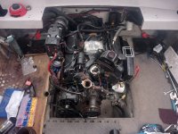
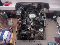
1996 Four Winns Sundowner with 5.0 Cobra engine and drive

Lou C

Supreme Mariner
Joined
Nov 10, 2002
Messages
12,653
The gauge to the left below the speedo is a gas fume detector. Every gas inboard should have one.
 

Lpgc

Petty Officer 1st Class
Joined
Jun 17, 2023
Messages
258
Thanks for all replies.

Gas fumes as in fuel or CO? That reminded me I may want to fit a new bilge blower and check routing of the blower ducting. The existing blower sounds like it has bad bearings but may just need cleaning out. There was a portable CO alarm fitted in the cuddy but its batteries are flat and looks old enough that I wouldn't want to trust it anyway, I might fit another one if I run the boat with the weather cover / bimini on.

I'll have a look at the fourwinns forum.

I haven't done much today, just reconnected the wires to the alternator so they run from the opposite direction to avoid being bunched up against the water pump area, connected a few more wires and tried to find out how the coil should be wired. I looked through all the pictures I took of the engine before I removed it but seems i didn't take any pics with a good angle showing the coil wire connections. The distributor is Prestolite but it has electronic pickup instead of points, it's obvious that the red and black from the distributor go to the + and - on the coil but it's the other coil wires I'm concerned about. There's a white and purple, I believe the white is for the tacho so goes to negative and the purple is ignition live so goes to +, is this correct?

Had a delivery of bolts today, walking across the yard carrying the bolts I tripped and landed badly enough on my knee to want to check I hadn't broken something before I got up. Did a bit more on the boat after but kneeling beside the engine was getting increasingly painful, then I had to take my son to the dentist, the knee feels increaingly worse and has swollen up so I spent the time after the dentist trying to confirm how the coil should be wired instead of soldering a couple of broken wires. Hope the knee is OK tomorrow because I have a new Barr manifold, riser and 3 V belts arriving tomorrow and intend on fitting them and the PAS pump.

I think I have the coil wired correctly but can anyone confirm?

Another thing - I made the mistake of re-attaching the mechanical fuel pump without cleaning its fuel connectors or draining the old fuel and I still need to refit the fuel filter / water separator. I want to pump the old fuel from the boat into some of my cars so I can refil the boat tank with fresh fuel. I have the idea of rigging an electric pump to draw/pump fuel from the tank through the mechanical pump, filter and pipes (to flush them all through) and pump it into my cars.. Is that possible or would the mechanical pump prevent the fuel flowing? If possible would I need to use a low pressure electric pump like a carb pump or could I use a fuel injection pump (I don't want to damage the mechanical pump etc)?

When I have the engine back together can I run it in the yard from a hose? I read (I think one of you mentioned it) that I can put a hose to the water inlet on the thermostat housing... But I presume if I do that I need to keep the raw water pump belt disconnected or it would burn the pump out? Does it matter if the drive is fitted? I would presume it won't matter because the raw water pump is inboard..
 
Last edited:

Lou C

Supreme Mariner
Joined
Nov 10, 2002
Messages
12,653
Gasoline vapor detector, which is a significant safety risk in inboard gas engines.
I'd like to answer your wiring questions but the only diagrams I have in my OMC factory shop manual are for the '88 Cobras, not sure if yours is wired different.
I have the wiring diagrams for both the GM and Ford engines.
For the Ford engines, the positive for the coil is connected to a purple/red wire that comes from the splice for the sense wire at the alternator, (this harness would run down the port side of the engine) and also there is a purple/black wire that goes from the coil positive to the I (ignition) terminal on the starter solenoid.
The negative terminals of the coil (grey wire) one goes to the wiring for the OMC ESA module (yours probably doesn't have being a cone clutch, you only have that on a dog clutch shifted drive) and also another grey wire on the coil negative goes into the harness with the big circular multi pin connector.
Unless someone has a later diagram, or a Volvo schematic for the same year that's all I got.....
As far as running the engine on the water hose, you need to feed the impeller housing water or else it will burn up. So either you disconnect the incoming water hose at the impeller housing and fab up a hose connection at the housing for a water supply hose, or disconnect the belt for the impeller housing and fab up a connection for the water inlet of the thermostat housing.
 

Lpgc

Petty Officer 1st Class
Joined
Jun 17, 2023
Messages
258
You're right it doesn't cut the ignition during shifting, no ESA fitted.

I was probably overthinking the coil wiring, thinking about it now I'm pretty sure I've got the ignition wires connected correctly. Just didn't want to risk blowing anything like the electronic ignition in the distributor or some unknown and difficult to find fuse etc.

Would it be OK to run the engine using muffs on the drive?

Any thoughts on my idea about running fuel through the mechanical fuel pump and water separator before I run the engine?
 

Lou C

Supreme Mariner
Joined
Nov 10, 2002
Messages
12,653
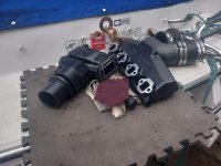
With the impeller mounted way up on the engine, you need to have tight fitting muffs and good water pressure, remember that the water has rise about 18" to the water hose that goes thru the transom and then about 3-4' forward to the impeller housing. So you can but have to have muffs that fit well. I like the Merc/Quicksilver muffs with the circular cups and metal rod clamp.
I'm not sure but I don't think you can draw fuel through the pump. Might just pump out the tank, and then fill the fuel filter with fresh fuel
What little is in the pump and lines probably won't matter much. You can also carefully disconnect the fuel lines to the pump and just drain them. What I do is loosen the mounting bolts for the pump first, that allows you to get the metal retaining collars loose without straining the threads. Same thing when re-installing the pump and carb, start the threads for the metal hard lines before bolting down the carb & pump, just install them loosely, then tighten the collars on the fuel lines, then tighten the mounting bolts. Some movement in the pump and carb allows the collars to thread in correctly. Works well.
BTW
you're lucky to have a simple engine with a mechanical pump and Holley carb. Much simpler, cheaper and easier to keep going than "better" fuel injection.
 

Lou C

Supreme Mariner
Joined
Nov 10, 2002
Messages
12,653
These, far better than the dual inlet tempo ones, the rubber on those is too stiff to seal.
 

Attachments

  • Merc Quicksilver muffs.jpg
    Merc Quicksilver muffs.jpg
    43.7 KB · Views: 0

Lpgc

Petty Officer 1st Class
Joined
Jun 17, 2023
Messages
258
I like the simplicity of a carb setup but I convert vehicles to run on LPG (propane) for a living so I'm clued up on fuel injection systems and would like the extra 20hp and better fuel economy fuel injection might give. That said I suppose given the age of the components a carb setup stands more chance of just working than an old injection system that might have clogged injectors or broken sensors. Still leaves the question is the carb setup correctly though... If it were a car I could check the mixture using an exhaust analyser but that's not so easy with the engine in the boat.

The reason I'm concerned about crap in the mechanical pump is because I left the pump fitted on the engine while I did a lot of work on it including honing the cylinders.. there could be any sort of crap inside it. If I could set up the cooling system to be able to run the engine then I suppose I could temporarily feed the carb from a fuel can and run a pipe from the output of the mechanical fuel pump to the outside of the boat into another fuel can to clean the pump and flush the lines...

I'll need to start thinking about rebuilding the carb soon, it's a Holley 2bbl, are they easy enough to tune after rebuilding? What mixture adjustments might be necessary? What rebuild kit would I need?

The only muffs I have are probably too small for the SX drive, I last used them on a boat I had with a mid 80's Merc 70 outboard that I rebuilt, inherited the muffs from my dad who used them on various outboards. I understand what you mean re loose fitting muffs, the inboard raw water pump must have self priming ability but wouldn't want it sucking on air. Another issue may be water pressure / flow rate from the hose, the house has unusually low water pressure. I thought about rigging something to attach a hose to the raw water intake on the flex plate that remains attached to the outside of the transom with the leg removed (I always forget the name of the internal and external transom mounted stuff), the other end of the hose into a bin full of water... If I could make a good seal between the hose and the water intake and keep the bin full of water would that work?

The bad knee slowed progress today but I soldered the couple of broken wires, cleaned up the exhaust Y, elbow and rubber exhaust pipes on the port side, the Barr manifold and riser I ordered yesterday arrived and I've removed the paint from the mating faces. I forgot which way up the lower rubber (that sits on the Y) fits, does it go shorter end up or longer end up onto the elbow?
 

Lou C

Supreme Mariner
Joined
Nov 10, 2002
Messages
12,653
Holley carb is about as simple as it gets. There will be a # on the air horn near there the choke valve is, that number is what you need to get the right kit. A mixture screw on each side of the fuel bowl & the auto choke adjustment is about it. A nice Holley 4 bbl on a Ford 4 bbl cast iron intake would really wake up that engine…but costs $$$.
See
www.holley.com
Bin of water won’t work. Must be pressure fed.
 

Lpgc

Petty Officer 1st Class
Joined
Jun 17, 2023
Messages
258
Holley carb is about as simple as it gets. There will be a # on the air horn near there the choke valve is, that number is what you need to get the right kit. A mixture screw on each side of the fuel bowl & the auto choke adjustment is about it. A nice Holley 4 bbl on a Ford 4 bbl cast iron intake would really wake up that engine…but costs $$$.
See
www.holley.com
Bin of water won’t work. Must be pressure fed.

Thanks for the carb rebuild info. Would prefer a 4bbl but I should make sure it runs before doing any mods. Early in the rebuild I considered swapping to aluminium heads and fitting a closed cooling system, I'd expect doing that along with the 4bbl would make a lot more power.

I mean feed the raw water pump from a bin of water, wouldn't that be just the same as the raw water pump having to pick up water from the leg anyway? I'm under the impression there's no pump in SX the leg, just the inboard raw water pump?

Done a bit more since my last post. This is the new Barr manifold and riser with machined faces cleaned up.

20240503_175101.jpg

Fitted the manifold but haven't fitted the riser yet

20240503_184758.jpg

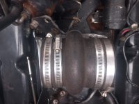
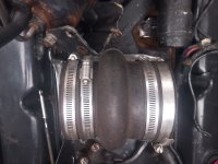
This is what I meant by the lower rubber being longer on one side than the other but I answered my own question by looking at the starboard side (I didn't remove the lower rubber on starboard side), the longer end after the bulge in the middle goes to the top onto the elbow, short end goes onto the Y

20240503_184827.jpg

I'm packing up for the evening now, my leg is giving me some pain but I'm glad I got the manifold on :)
 

Attachments

  • 20240503_175101.jpg
    20240503_175101.jpg
    2.7 MB · Views: 1
  • 20240503_175058.jpg
    20240503_175058.jpg
    2.6 MB · Views: 1
  • 20240503_184800.jpg
    20240503_184800.jpg
    3 MB · Views: 1
  • 20240503_184828.jpg
    20240503_184828.jpg
    1.1 MB · Views: 2

Lou C

Supreme Mariner
Joined
Nov 10, 2002
Messages
12,653
Well the only way that would work is if the bin was higher than the level of the raw water pump on the engine. The way the cooling system works, when the boat is in the water, hydrostatic pressure forces water up the outdrive water intakes, through the hoses that lead to the pump, because when the boat is in the water, all those hoses are below the water line of the boat. So if you had the boat in the water, and you disconnected the feed hose at the impeller housing, unless you held it up, water would flow into the boat. The impeller does not suck water, against a column of air, which is what will happen with trying to suck it from a bin. It can only move water, if that feed line is fully filled with water.
In fact what I do to avoid burning up a perfectly good impeller at the start of each season:
hook up water muffs
turn water on
go up to engine, disconnect the water inlet hose at the thermostat housing
fill that hose fully with water
reconnect hose
that way I'm sure that the impeller housing (which on the dog clutch Cobra, is in the upper gear housing of the outdrive) is full of water. The pump will prime instantly that way.
been doing this a long time, learned all the ins and outs of it....
 

Lpgc

Petty Officer 1st Class
Joined
Jun 17, 2023
Messages
258
Well the only way that would work is if the bin was higher than the level of the raw water pump on the engine. The way the cooling system works, when the boat is in the water, hydrostatic pressure forces water up the outdrive water intakes, through the hoses that lead to the pump, because when the boat is in the water, all those hoses are below the water line of the boat. So if you had the boat in the water, and you disconnected the feed hose at the impeller housing, unless you held it up, water would flow into the boat. The impeller does not suck water, against a column of air, which is what will happen with trying to suck it from a bin. It can only move water, if that feed line is fully filled with water.
In fact what I do to avoid burning up a perfectly good impeller at the start of each season:
hook up water muffs
turn water on
go up to engine, disconnect the water inlet hose at the thermostat housing
fill that hose fully with water
reconnect hose
that way I'm sure that the impeller housing (which on the dog clutch Cobra, is in the upper gear housing of the outdrive) is full of water. The pump will prime instantly that way.
been doing this a long time, learned all the ins and outs of it....
I think you mean the pump can't self prime but is normally below the water line?

In that case would the bin idea work if the level of water in the bin were above the pump?

Even if I don't go with the bin idea (I'll decide after reading your answer) I would (like you) want to prime the pump and engine block with water.

I think you know mine is the '96 Cobra that uses the SX drive, I understand the raw water pump is inboard on the SX setup (no pump in the leg)?

I suppose even in the worst case I could use something like a garden pond pump to lift the water from the bin to the water inlet?
 

Lou C

Supreme Mariner
Joined
Nov 10, 2002
Messages
12,653
Correct the pump is normally below the water line of the boat and it can’t self prime if that water inlet hose isn’t full of water. If you could elevate the bin higher than the impeller housing like on the swim platform of the boat and keep the bin full feeding it from a garden hose that might work assuming that the muffs fit tight. Otherwise you’ll be frustrated by burning up impellers. It’s just how it is. Even with a Merc Alpha drive which has the impeller in the lower unit; the water level has to be higher than the impeller to fill the housing. Like about 2” above the anti ventilation plate on the outdrive.
 

Lpgc

Petty Officer 1st Class
Joined
Jun 17, 2023
Messages
258
I'm honestly not sure if the pump is or isn't always below the water line or if the pump does or doesn't have a small amount of self priming ability but I take your point re priming. Just going on memory which could be wrong I seem to remember the water inlet port on the leg being around level with the water line when the boat is moored, give or take a couple of inches. I'd expect it to be able to self prime a couple of inches?

What I meant was fit a pipe to the water inlet on the outside transom fitting with the drive removed and make sure it's water/air tight. I still take the point about the bin being higher than the water inlet and the implied point that there shouldn't be much of a inverse U bend coming out of the bin (unless I use a pond pump).

When it's all back together I'd like to run the engine in the yard before refitting all the trim (rear seats, engine cover, etc). Doing that I'll be able to check for things like the engine will actually run, no nasty noises, good oil pressure, no water entering oil, doesn't overheat, etc, before doing the extra work of refitting the trim and taking it to the river. If it runs in the yard OK I'll feel confident to refit the trim and take family on the first outing to the river, then hopefully use it on lakes then the sea. If it fails tests I'll need to pull the engine agian but at least I won't have wasted time refitting trim or towing it back and forth.
 
Last edited:

Lou C

Supreme Mariner
Joined
Nov 10, 2002
Messages
12,653
Ok you might be able to connect your water hose to the water fitting in the pivot housing (the part the outdrive bolts to) as long as the bin is elevated above the level of the impeller. To test: disconnect the feed hose from the transom at the impeller housing, water should flow out of that hose. Remember it’s not just water pressure (these systems are low pressure actually) but water volume; it takes a large volume of water flow to carry away the heat of the engine & exhaust.
 

Lpgc

Petty Officer 1st Class
Joined
Jun 17, 2023
Messages
258
Thanks.

Would it be OK to rig an external pump (say pond pump) to feed the engine with water from a bin when the engine isn't running, or would/could that lead to water entering the engine cylinders? Looking at the design of the riser outlets and the angles involved it seems it wouldn't take much for water to flow the wrong way if the engine isn't pushing exhaust gas. This could raise the question is it better to turn water on first and risk water entering cylinders or turn water on after starting the engine and risk damaging the circulation pump and/or raw water pump (if not bypassed and V belt connected).

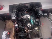
Done a bit more today, fitted the port side exhaust components.

20240504_183013.jpg

Hope I've fitted all the exhaust rubber pipes properly... Do the clamps have to be in a specific position such as above/below the flapper shafts, in a specific position on the risers?

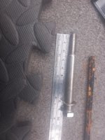
Realised I need to change to a couple of longer bolts on the water pump to allow for the thickness of the PAS pump bracket, the PAS bracket bolts to the 2 outer 2 bolts at the 1 and 2 O'clock position on the water pump, I have a longer bolt for the 1 O'clock position but will need to buy another bolt for the 2 O'clock position, both need to be about 1/4" longer than those I fitted when I rebuilt the engine. Hope removing and refitting WP bolts doesn't cause a problem with the gaskets.
 

Attachments

  • 20240504_184206.jpg
    20240504_184206.jpg
    1.5 MB · Views: 3
Last edited:

Lou C

Supreme Mariner
Joined
Nov 10, 2002
Messages
12,653
About the pump, I’m not sure because I don’t know how many gallons per hr it flows Vs how much the engine needs. You might be able to find out how much the impeller flows at idle speed and as long as the pump flows that much it should be ok. I can’t recall exactly how I installed my exhaust rubber parts but I’m going to start getting the boat ready for the season in the next few days so I’ll be able to get a pic of it. I used the same Barr exhaust (except mines a Chevy V6) and those alu exhaust pipes the go between the rubber hoses are a different shape on the V6. I never had problems with the engine ingesting water running it on the muffs for years.
 

Lpgc

Petty Officer 1st Class
Joined
Jun 17, 2023
Messages
258
Thanks Lou.

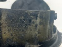
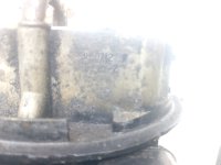
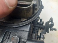
I haven't done much with the boat since my last post. The longer bolt I ordered and thought I needed to attach the PAS pump to the alternator hasn't arrived yet but I found the stainless bolt that was originally in that position (at least when I bought the boat) and have fitted the PAS pump. I ordered it from Amazon thinking it would arrive before 1pm today but it''s a bank holiday in Englad and it seems Amazon don't deliver on bank holidays in my area. I also ordered a 1/2" screwdriver bit to change the oil in the leg from Amazon, should all arrive tomorrow but I probably won't get time to work on the boat tomorrow. Unscrewed the fuel filter from its housing, it was on very tight. Thought I'd misplaced the carb spacer (which has inlet for a PCV / breather), looked in the boat for it, looked in the garage, wasetd half an hour, found it attached to the inlet manifold fitted on the engine lol, I'd taped it up to prevent anything falling in. Took some pics of the carb and found the number 3850712 on it.

20240506_153114.jpg

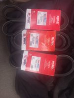
A marina advised these belts... Turns out made in China, hope they're OK

20240504_181508.jpg


I think the next things I'll do are hand crank the engine again (just to be sure), fit the new spark plugs, plug leads, rotor arm and dizzy cap. I'll be looking for a rebuild kit for the carb but don't know whether to rebuild it before trying to start the engine or test if runs OK then rebuild the carb... Any advise on the carb rebuild?

Does this rebuild kit seem correct for my carb? https://repowermarine.com/carb-rebuild-kit-for-4-3-5-0-5-7-volvo-penta-omc-replaces-3854020.html Mine is a 5.0 but Ford not Chevy, the 4.3, 5.0, 5.7 list suggest Chevy to me...
 

Attachments

  • 20240506_153053.jpg
    20240506_153053.jpg
    2.2 MB · Views: 3
  • 20240506_153008.jpg
    20240506_153008.jpg
    2 MB · Views: 3

Lou C

Supreme Mariner
Joined
Nov 10, 2002
Messages
12,653
Volvo Penta & OMC did use Holley carbs on GM engines, especially after 1990 when Rochester stopped making carbs.
 

Lpgc

Petty Officer 1st Class
Joined
Jun 17, 2023
Messages
258
Still need a rebuild kit for the 3850702 Holley 2bbl carb. I phoned the marina (link above) today, they told me they couldn't guarantee the rebuild kit they list would be compatible with my carb. I think there's a good chance it would be compatible but I'd rather buy one that the seller says is compatible.

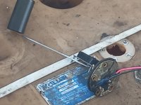
I removed the level sender to see if the hole would be wide enough to lower the fuel injection pump into the tank through it, the hole isn't wide enough. But I did find the fuel level sender is broken, it's seized so the float arm couldn't rise on the fuel, so I'll be needing a new fuel level sender.
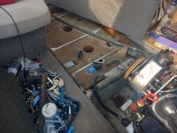
More problems found today. Plan was to empty the boat fuel tank by pumping fuel out of it using a pump connected to the fuel line. The first few pints I'd pump into glass cookware jugs to check condition then if the fuel seemed OK pump the rest of it into my car and jerry cans. The pump I used isn't self priming so I only managed to pump a few pints out anyway... but those few pints contained water :-(. I had left the boat with the tank full of E5 last year to full to help prevent condensation and didn't seem to have any problems with water in fuel when I last used it so I don't know where the water came from. Removed the level sender to see if the hole would be wide enough to lower the fuel injection pump into the tank through it, the hole isn't wide enough. But I did find the fuel level sender is broken, it's seized so the float arm couldn't rise on the fuel, so I'll be needing a new fuel level sender.

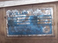
20240508_161955.jpg

20240508_164819.jpg

20240508_162017.jpg

I ordered a low pressure pump that should be self priming so I hope to be able to pump the rest of the fuel out using that.

Took one step backward today, removed the mechanical fuel pump, thought it better to remove it to flush it through with fuel from a jerry can I pumped out of the boat tank... didn't even manage to get any good fuel out of the boat tank into a jerry can. I suppose at least I know of a good reason why the fuel gauge didn't work.

Does anyone know if the level sender (for the 1996 car instrument cluster style Four Winns gauges) should be 240>33Ohm or 0>160Ohm?

I forgot to measure the tank depth. Can anyone tell me the depth from the tank model number Moeller 2910?
 
Top