1976 Tom Boy Boat, 1976 40 HP Johnson Outboard and who knows what Trailer

gm280

Supreme Mariner
Joined
Jun 26, 2011
Messages
14,605
Well more work has gone on. And some not picture worthy because you can't see it.

I managed to install the bilge pump hull fitting today. I can tell you, the hull is tough stuff. I had to drill a 3/4" hole for the fitting and I drilled it on the starboard side back by the transom. WOW, that fiberglass is hard and thick. It is at least a 1/4" thick or more and no wood, just glass, and a forstner bit sure had its' time cutting through. But now that is all finished.

Why is it every time you decide to attach anything on a boat, you have to adjust for other things in the way? I guess that is another of Murphy's Laws. The place I originally wanted to drill the hole for the out flow bilge fitting was in line with an extra screw that was used to fit the anchor light fixture. So I had to move the place to avoid that fixture. But it all worked out in the end.

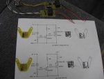
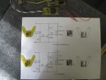
I also finished building the last two circuits for the meter panel. They look odd, but were designed for where that will attach. Once they are totally finished, they will be enclosed in resin. So if anything ever happens to either of them, I'll just built a new one, that way they will be totally impervious to any water, moisture, oils. fuels or vibration.

So with the exception of pulling a few more wires, I can finish wiring up everything. YES, I still have to make the live well cushion seat, and am putting that off until...well I don't know until.

I also have to work one of the two 6 gallon metal fuel tanks as well. I have to strip them and prime and paint them and that is come real soon.

I have installed the front battery box (trolling motor battery) and strap connectors. I am working on the transom mounted battery (cranking) box now. It is taking a little longer since I don't want to drill any holes in the transom or floor. I will post that setup when finished.

And then the engine install...YEAH!
 

Attachments

  • photo309386.jpg
    photo309386.jpg
    68.3 KB · Views: 0
  • photo309387.jpg
    photo309387.jpg
    80.1 KB · Views: 0
  • photo309388.jpg
    photo309388.jpg
    80.2 KB · Views: 0

gm280

Supreme Mariner
Joined
Jun 26, 2011
Messages
14,605
Why not just glass ,fair, and paint ...
No rule says ya gotta have a cap ..
Unless you just want one for looks or something ...

You know the more I think about this the more your idea is starting to make more sense.

I have tried a few of the previous suggestions with the exception of brazing the aluminum idea. And that isn't off the table either. But maybe I should just apply a few more layers of CSM and fair it out and see how that works.

The making a cap with a mock-up of the transom sounded like a viable idea, but the end results don't look as great as I would have thought. Hard to get everything laid down and straight. Wavy top and worst sides makes it look more like a twizzler instead of a transom cap.

And I was very hopeful with the PVC idea as well. I cut the PVC pipe and heated it and the first attempt had some burnt issues. So cur another piece and couldn't get it to lay down on top and the sides at the same time. A better form could make that work (?) and that too isn't off the table yet either.

If the transom didn't have wood grain showing up I would just try to seal it and move on. But I am afraid it would allow water in without any obstruction whatsoever. So that has to be fixed first if I am to CSM and poly over.

If I could get 1708 to fold nicely over the two sides of the transom, that would be the best idea. But I can't even get CSM to fold over a square edge and stay laid down without rounding up as it cures on the edges. So 1708 would never do trying to make it lay flat on the sides and top.

We will see. Getting too close to stop now...
 

sam am I

Commander
Joined
Jun 26, 2013
Messages
2,169
I also finished building the last two circuits for the meter panel.


If I might offer a small mod/option to your low batt circuit?

As designed(left bottom), the low batt indicator LED will be dimming/fading out linearly (See LED current, ID2) as B+ begins to drop due to the LED is being driven with a constant voltage source(B+). This is possibly not desirable especially at different viewing times/conditions .

This can be improved (small mod) upon by driving the LED with a constant current source config(Ic-Q1)... (right top/bottom). As seen, the LED will stay same brightness and run at a constant lit level from around 12V-3V (Notice LED current, upper right, ID2) over the same range until it blinks out at around 3V.

Click image for larger version  Name:	Low Batt LED_1.jpg Views:	1 Size:	240.8 KB ID:	10716211


Just a thought to consider gm,
 
Last edited:

sam am I

Commander
Joined
Jun 26, 2013
Messages
2,169
I usually use a hole saw, I bet a forstner would take a while!

The minute steel blades (any) hits fiber glass, its over, they are dulled in a heart beat.

I learned that the hard way I guess with a band saw some years back, just going through fiber glass in small PCB's I was cutting out, glass ruins even high end bi-metal blades the sec it touches it.
 
Last edited:

gm280

Supreme Mariner
Joined
Jun 26, 2011
Messages
14,605
If I might offer a small mod/option to your low batt circuit?

As designed(left bottom), the low batt indicator LED will be dimming/fading out linearly (See LED current, ID2) as B+ begins to drop due to the LED is being driven with a constant voltage source(B+). This is possibly not desirable especially at different viewing times/conditions .

This can be improved (small mod) upon by driving the LED with a constant current source config(Ic-Q1)... (right top/bottom). As seen, the LED will stay same brightness and run at a constant lit level from around 12V-3V (Notice LED current, upper right, ID2) over the same range until it blinks out at around 3V.


Just a thought to consider gm,

I also thought about that and did testing to see how dim it got before it stopped illuminating. It really has to get pretty low for that to happen. And on the low fuel side, I used a dedicated 12 volt source for that LED.

But I have to say, you are the first one to think about that as well. Thumbs up for you. When designing and building one-off or unique circuits, you always breadboard them first off before making any PC payout.

I set the low fuel level about 1/3 tank level. The battery low level is around 12.1 to 12.3 level. And I have a switch to monitor either the cranking battery or the trolling motor battery.

Yes way too much for such a dinky little stick steering boat. But What can I say...

Thanks for checking behind me. Always great to have other examine your ideas.
 

sam am I

Commander
Joined
Jun 26, 2013
Messages
2,169
Yeah the low fuel is a moot point, saw that but, the low batt LED's intensity deviation over some/a range caught my eye. Yes, probably be a darn weak battery before it'll dim out, was thinking maybe in the sun or something you'd maybe want/need it as bright as it runs at 12V when it was, say at like 10'ish V...

Was thinking, approx down 2 mils @ 10V from 8 mils @ 12V, ya loose 1/4 of the intensity, not sure if that was too much or not, depending of course.

Like the addition of the integrated lights, super cool gm!

Wanna now make'umm blink on and off at progressively high rates and intensity's as they approach critical levels??? :lol: Could code you up a 8 pin SOIC micro that'll do it all and then some :eek:
 
Last edited:

gm280

Supreme Mariner
Joined
Jun 26, 2011
Messages
14,605
Yeah the low fuel is a moot point, saw that but, the low batt LED's intensity deviation over some/a range caught my eye. Yes, probably be a darn weak battery before it'll dim out, was thinking maybe in the sun or something you'd maybe want/need it as bright as it runs at 12V when it was, say at like 10'ish V...

Was thinking, approx down 2 mils @ 10V from 8 mils @ 12V, ya loose 1/4 of the intensity, not sure if that was too much or not, depending of course.

Like the addition of the integrated lights, super cool gm!

Wanna now make'umm blink on and off at progressively high rates and intensity's as they approach critical levels??? :lol: Could code you up a 8 pin SOIC micro that'll do it all and then some :eek:

Yes this is the problem when I build things. I could program a lot of microcomputers to do basically everything on the boat. But, in this little stick steering setup, even a tach is over kill. I had to make myself stop with the unique circuits for all types of fancy, but certainly not needed, circuits. When you worked 38 years in electronics, programming and circuit design, it makes you do things you know are never needed but nice... :doh:
 

gm280

Supreme Mariner
Joined
Jun 26, 2011
Messages
14,605
Well it's been a while since last update. The reasons range from nothing much to show picture wise, and we were on a vacation. Now that we returned and allowing everything to get back to "normal" again, I don't have much to post about anyways. More work on the cranking battery mount and working on the gas tank mounting setup.The battery box mount came out pretty nice and solid, and no holes drill into the floor or transom either. :D

Trying to make a gas tank mount that will both hold the 6 gallon metal tank solid but removable when need be, AND not mark it up from vibration while running. However, I once again ran out of 435 polyester resin. So I ordered another gallon from US Composites. Now wait a couple days to get back to that issue. :whistle:

With the exception of finishing up the wiring, that is about it. Well I still have to cap the transom top and sew up the live well seat cushion too. Putting that off until the very last thing. :facepalm:

Still amazing how many wires this little boat takes to get everything wired. Too many niceties I guess. Lesson learned for next time. :loco:
 

gm280

Supreme Mariner
Joined
Jun 26, 2011
Messages
14,605
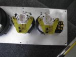
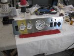
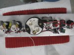
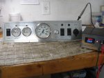
More wiring and near done. I still have some more wiring, but I am really getting close now. Since I built a few circuits for this boat, I had to mount them in place and wire them and test before installing for final. Once I proven they worked correctly, then I mixed up some JB Weld and covered them to keep them waterproof and vibration free. I still have a couple more circuits, but here is the meter panel about ready to install now.

The first two pictures are the meter panel how it looks now and then the wires behind it. If you look in the left side of the behind the meter panel picture, you can see two circuits with JB Weld covering. Those two circuits are the low battery voltage(s) circuits for both the cranking and trolling motor batteries. The next one is the low fuel level circuits. It lights when the fuel level is at 1/3rd fuel remaining.

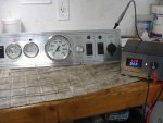
The next picture shows a setup with my power supply showing the far left light not illuminated LED because the voltage is at 12.4 volts. The next picture shows that LED lite because I dropped the voltage to 12.0 volts. I have it set at about ~12.2 to 3 volts at the turn on level. And if you flip the switch next to the meter, you can monitor either the trolling motor battery or the cranking battery.

They all seem to work perfectly. Also in the picture of the wiring behind the meter panel there is a variable aerator circuit that allows you to adjust how long it takes to aerate the live well. Hard to see because it is mounted in a more vertical setup. That circuit board was cleaned and then heavily coated with clear lacquer to make it waterproof.

I am presently boxing the auto bilge pump circuit in a very small plastic construction box to mount behind the main control panel. So still some wiring but pretty close now.

Like I previously stated, when wiring circuits there really isn't much to show picture wise.

Until next time...
 

Attachments

  • photo310427.jpg
    photo310427.jpg
    77.2 KB · Views: 0
  • photo310428.jpg
    photo310428.jpg
    74.6 KB · Views: 0
  • photo310429.jpg
    photo310429.jpg
    77.7 KB · Views: 0
  • photo310430.jpg
    photo310430.jpg
    80.3 KB · Views: 0

sphelps

Supreme Mariner
Joined
Nov 16, 2011
Messages
11,468
Holy smokes GM , I would be pulling what’s left of my hair out trying to figure out all that circuitry !
:hail: You certainly have the knack for it !
 

gm280

Supreme Mariner
Joined
Jun 26, 2011
Messages
14,605
Holy smokes GM , I would be pulling what’s left of my hair out trying to figure out all that circuitry !
:hail: You certainly have the knack for it !

Actually it is not as scary as it initially appears. You don't look at everything at once. You work each circuit by itself. And doing that, It is very easy to wire. It just takes a long time to crimp and solder every connection.

I need a few bullet type connectors as well yet. And while I have lots of them, I don't have any female types. So I ordered some. And looking for female bullet connectors, you can find tons of males connectors, but not so with female types. Odd isn't it. I mean how are new ones made? :noidea:

I still have a nice project coming up for this boat project. I am going to refurbish two 6 gallon metal tanks to new condition and use one in this boat project. I may make a separate thread just for that tank project. I have two that are in very good condition both in side and out with the exception of the faded paint and insignias. No dents or rust to speak of. Both are OMC type tanks with one being an old Johnson style and the other actually an OMC. Should be real fun to refurbish...
 

kcassells

Fleet Admiral
Joined
Oct 16, 2012
Messages
8,737
Ya know GM was here too, he has skills! :D

The atomic age began on
July 16, 1945, when the Manhattan Project detonated its first successful nuclear weapon test in the New Mexico desert.
 

Hab

Petty Officer 2nd Class
Joined
Jul 4, 2017
Messages
158
Great work GM, your work looks as good or better than any of them high end auto restorers.
 

gm280

Supreme Mariner
Joined
Jun 26, 2011
Messages
14,605
Thanks sphelps, kcassells, Hab and Sam i am, for the kind words.

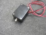
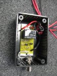
While not finished with all the electrical (parts ordered...again) it is very close. Yesterday I wired up the auto bilge circuitry and installed it in a plastic, hopefully, water proof box after cleaning the circuit board and wire connections and spraying them with a few coats of clear lacquer. I used a BNC chassis connector so the BNC cable can merely plug in. And since the BNC is stainless steel I con't see any corrosion issues either. The three wires coming out of the box will connect to the control panel switch. Ad they too will be labeled.

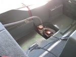
I also cut a hole in the batterny box top for the Perko A/B battery switch. And finished up the transom mounts for the hold down straps for both the cranking battery box and the 6 gallon metal fuel tank. The reason I built those transom brackets is to keep from drilling any holes into the transom. Those adapters are polyester-ed to the transom to stay. And while all those things are not earth shattering issues, it does take a lot of time to do them all the same. And it is all such little issues that take more time then I would have thought.

When you build things like a new transom and/or stringers and flooring and such, you get to see huge changes and it makes your efforts seem so much worth the time. But when you get to the little things, it takes a lot of time without much evidence to show. And that IS where I am presently at... :cool:

Of course in-between those "little" issue I mowed the yard, edge, trimmed, blew off all the clippings, cut three trees down and cut them up and piled them to maybe burn, and washed all the yard equipment. Life has many on-going projects... :D

Until next time, have a great day! :thumb:
 

Attachments

  • photo311464.jpg
    photo311464.jpg
    109.9 KB · Views: 0
  • photo311465.jpg
    photo311465.jpg
    118.5 KB · Views: 0
  • photo311466.jpg
    photo311466.jpg
    74.3 KB · Views: 0

gm280

Supreme Mariner
Joined
Jun 26, 2011
Messages
14,605
Have a splash date set yet? Fantastic work as always.

Well no I don't. But there is a really good reason.

When I first started this BOAT PROJECT, years ago, I thought it was merely a few moths ordeal at best. So any possible prediction would be a lie. Not an intentional lie, but a lie all the same. So it will happen hopefully some time this year...I guess. :decision::noidea:
 

gm280

Supreme Mariner
Joined
Jun 26, 2011
Messages
14,605
Okay, I think I can now say that I finished pulling wires from the transom of the boat to the control panel. Seems every time I thought I finished, two more wires were needed. :facepalm: :frusty:

I now wonder if I over exceeded the carrying capacity of the hull just in copper? :doh:

I still have a few to pull from the control panel to the meter panel and connect, but those are merely short distances and hope to be a lot easier.

I will say I have a lot of lessons learned for later.

I ordered the trolling motor panel receptacle and cable ends for the trolling motor. And like a total idiot, I ordered via pictures and not descriptions. I know you can see where this is headed. Seems Female cable ends won't fit Female panel receptacle even though they look like they could. And two wire setups won't work with three wire setups. So back to the drawing board and reorder the correct items this time. :violin:

If there is anything I haven't screwed up with this boat project, I can't think of it! I do remember telling my two boys that when you screw things up, it is a learning experience. And they told me, if that were true, I'd be an Einstein by now.

But I continue and one day....one day, I will finish. The only other long wire I can possibly think of pulling to the front is a depth locator transducer cable. Other then that, I think I got everything else pulled. We will see... :D
 
Top