1974 Duo Vagabond 17' sterndrive Transom and stringers project

Redtruck12

Petty Officer 1st Class
Joined
Jan 25, 2018
Messages
344
Update time again
i had been hesitant about poring the foam and concerned that my cavity temperature would be substantially lower that the surrounding temperature I can create with propane heaters in my tent.
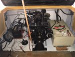
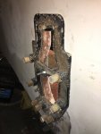
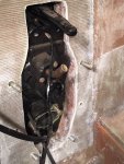
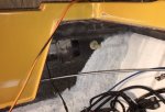
i had completed the install of the additional bulkhead to enclose the centre channel at approx 3 feet from the stern and feel that limiting the opportunity for water to potentially get forward of my repair area is the wisest way to go.
the bulkhead was a bit of a pain to install as it is recessed under the already installed decking but went in well. I floated all the edges in P.B. And will reinforce with csm and or 1708 to be sure it is securely sealed.
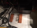
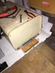
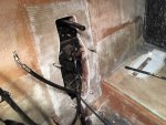
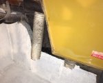
as for the foam; I was pleasantly surprised at the expansion.
my temperature was 80-85f and I did my best to circulate air inside the cavity before poring the foam. My 2 side chambers required 2 one litre pores to completely fill with a good ooze from expansion holes which was much less than I figured.
Leaving me with what should be enough to completely fill the forward section of my centre channel running to the bow.
 

Redtruck12

Petty Officer 1st Class
Joined
Jan 25, 2018
Messages
344
Update time again.
well my estimation on foam down the centre channel came up about 3 feet short, roughly to the dash and steering controls😕 I’m debating whether to leave it at that with roughly 6 feet of “bonus foam from how it came from new or buy more foam.
any thoughts?
2 quart kit will not likely fill it and 2gallons will be way more than I need.
still finishing my final layer of tabbing on the forward section and waiting till all my foam pour holes are filled.
spent tonight getting my keyhole thickness over the minimum 2” by adding 2 layers of 1708, in preparation for drilling this weekend.
BIG shout-out to Desmond (Capri 1750 complete rebuild and 9 months to do it) who live less than an hour away AND has agreed to lend me the MC-1 drilling jig he came across
thanks again Dez👍

Next thought , is final coat and finish of the inside of the floor.
originally was carpet but I’m not sure I want to go that way again.
possibly some snap in runners but not full wall to wall carpet🤔
so gel cote?
tractor paint??
some type of textured coating?

looking for suggestions, recommendations
 
Last edited:

chevymaher

Commander
Joined
Mar 29, 2017
Messages
2,915
I got foam left from doing mine. Me I want it all full mine only had rot when there was a gap in the foam.
 

Redtruck12

Petty Officer 1st Class
Joined
Jan 25, 2018
Messages
344
Well transom total thickness is good and I was able to meet up with Dezi and borrow the MC-1 out drive drilling jig he had on hand. Thanks again Dezi! Great to meet you in person and tour your project.
spent a bit of time lining the jig to what remained of my original hole locations and started drilling! It was really nice to not have to worry about being crooked when drilling and the jig works awesome
 

Attachments

  • photo311519.jpg
    photo311519.jpg
    2.2 MB · Views: 0

Redtruck12

Petty Officer 1st Class
Joined
Jan 25, 2018
Messages
344
I Do have a couple questions and hoping for some more advice;
i ordered new lower bolts and anodes which came with 2 rubber washers? I assume they go on the bolts, between the bolt and the gimbal housing??? Or do they go under the anode?
I also ordered a replacement cork gasket that goes between the transom and the gimbal housing. Other than re applying poly resin to the new holes I just drilled thru the transom... what sealant should I be using?
 

Attachments

  • photo311527.jpg
    photo311527.jpg
    162.5 KB · Views: 0
  • photo311528.jpg
    photo311528.jpg
    847.5 KB · Views: 0
  • photo311529.jpg
    photo311529.jpg
    1.4 MB · Views: 0
  • photo311536.jpg
    photo311536.jpg
    861.8 KB · Views: 0

Redtruck12

Petty Officer 1st Class
Joined
Jan 25, 2018
Messages
344
That’s what I thought but looks like there are 2?
 

Attachments

  • photo311562.png
    photo311562.png
    119.4 KB · Views: 0

chevymaher

Commander
Joined
Mar 29, 2017
Messages
2,915
On mine 20 was rubber between the bolt and gimble. 19 the one between the bolt and the anode was a lock washer. Now the bolt is square on the gimble side. Make sure it is clocked right. It likes to turn tightening and makes it leak. Hard to tell if it turned from inside the boat. Ask me how I know.
 

Redtruck12

Petty Officer 1st Class
Joined
Jan 25, 2018
Messages
344
Thanks Chev!
I asked the same question separately in the mercruiser section and got a different answer 🤔
Bondo says rubber under the anode which kind of makes sense as they came packaged with the anodes. And nothing??? But sealant on the bolt into the gimbal...
only issue is I have the remains of 1 from the old bolts and it is either cut square or squished square in the centre!
i don’t know but sure don’t want any leaks after all I have done.😐
confussed
 

chevymaher

Commander
Joined
Mar 29, 2017
Messages
2,915
Well my boat was owned by a actual mech who works in a marina for a living. I am not making any right or wrong claims. Just what I based my assembly on. When I took it apart.

It had the rubber between the bolt and the gimbal. And a washer under the anode. Made sense to me the anode is not supposed to be grounded/isolated from the bolt. Its job is to pass current and be sacrificial. Looses metal to the water faster than the gimbal in a electro chemical reaction. Thus saving the gimbal from eroding.

Important thing is is don't leak. I just followed what I saw when I took it apart and the online drawing I found matched what I saw taking it apart. It labeled the parts. I did as they told you to and used 4200 generously as I assembled it.

On the gimbal there is a square inset the square on the inside of the bolt fits into. My best advice is just clock it correctly. Have someone hold it and climb into the boat and tighten it while they hold pressure so it can't turn.

I may be wrong but it works.
 

Redtruck12

Petty Officer 1st Class
Joined
Jan 25, 2018
Messages
344
Well I ordered and received a tube of 3M 4200 and enough 2part foam to fill my remaining bow section of the centre channel.
my current plan is to have everything finished, sealed, sanded and painted within the next 2weeks. Planning on prime and cream / off white colour with tractor paint (Tremclad) with hardener. Will figure out carpet etc
I have been chipping away at reassembly of the engine after having the cylinder head reworked and will need to trailer her to my work to reinstall the engine.
will still need to finish mounting the fuel tank, battery box and smaller items like bilge pump and hose, blower vent tubes and other small items
this weekend I hope to have all my final glasswork completed.
thinking ahead as much as I can and know I will need to get my hands on an alignment tool to realign the engine to the gimbal housing 🤔
 

Redtruck12

Petty Officer 1st Class
Joined
Jan 25, 2018
Messages
344
Update time again.
lots happening in the last couple weeks.
been fighting time and set myself a deadline to be ready to drop the engine in this weekend.
final finish of the transom exterior was a battle (recent thread “tractor paint hellp” but did get things sorted and very happy with the final finish, coat of interior paint in the engine bay (leftover from the exterior transom painting, gimbal installed, cables and controls organized and routed.
today was my deadline to get the ol girl ready and mobile to take to work and install the engine.
everything went as planned and as I hoped.
still have some final glassing forward of the engine bay but no interference with the engine.
only 1 screw up!

When installing the exhaust riser I over tightened the mounting bolts at the gimbal housing and cracked it 😕😡
i have a buddy that does aluminum repair and welding but it’s a long /holiday weekend. I will contact him on Tuesday, looks like a straight forward repair BUT....
now that I have the engine in place in not sure if I can weasel that riser pipe in and bolt it up.
worst case will be shifting the engine forward to get it in.
anyone know if you can get that riser pipe in and out with the engine in place (1974 Mercruiser 4 -140hp)????
 

Attachments

  • photo312737.jpg
    photo312737.jpg
    127.5 KB · Views: 0
  • photo312738.jpg
    photo312738.jpg
    142.1 KB · Views: 0
  • photo312739.jpg
    photo312739.jpg
    93.1 KB · Views: 0

Redtruck12

Petty Officer 1st Class
Joined
Jan 25, 2018
Messages
344
Well been chipping away at things.
been over a year since the engine came out and everything got disconnected and I have been sorting out the mess of wiring from 40 odd years of patch work and add ons. I have things somewhat cleaned up and figured out.
bilge pump installed tonight, just need to plumb it after the silicon cures.
installed the trim actuator and ran the hydraulic lines.

not sure how is best to run the tubing for my venting.
What I took out on my gut last spring was a mess
the setup I have is a fan motor exhausting out the starboard vent thru what looks like drier vent duct tubing and 2 tubes(same stuff) connected to the port side vent.
where in the engine bay should the tubes/ducts end???
in the bilge?
down low at floor height?
 

Attachments

  • photo313331.jpg
    photo313331.jpg
    98.9 KB · Views: 0
  • photo313332.jpg
    photo313332.jpg
    100.2 KB · Views: 0
  • photo313333.jpg
    photo313333.jpg
    139.7 KB · Views: 0

Redtruck12

Petty Officer 1st Class
Joined
Jan 25, 2018
Messages
344
Another question I have is my front mount which sits directly on my decking.
it was originally lag bolts but I am thinking nut and bolt.
i have access from the underside and reinforcement glassed to the stringers.
any thoughts on nut and bolt?
 

Redtruck12

Petty Officer 1st Class
Joined
Jan 25, 2018
Messages
344
Update time again
life has been buggering up boat time over the last couple weeks but chipping away at little things when I can.
wiring is about 90% complete I figure.
was waiting on a few little parts, manifold gaskets, tuneup parts etc. And still had to re install the exhaust elbow that I cracked by over tightening.
had to shift the engine off it’s mounts to sneak it in. Was able to slide it with 1 rear bolt and the front mount bolts out and did not have to lift the engine. Some grunting and cursing but it’s in now 😁
still need to mount and plumb the fuel tank and mount the battery box. Planning to glass in a sacrificial plywood base for both and then screw into it. I have managed 0 holes in my decking so far and plan to keep it that way.
test fit the lower engine bay divider that the engine cover sits on and fits well. It is bare wood with carpet and still needs waterproofing (resin and csm) before final assembly.
I have tracked down an alignment tool for rent locally and hope to get my engine alignment set within the next week.
Still need to glass in seat attachments as well but undecided on whether to put the back to back / headknocker seating back in for the season on converting to swivel bucket seats now as opposed to over the winter when I redo all the trim and interior.
I had already decided that I would rather have the additional floor space to the fold flat seats.
 

dezmond

Senior Chief Petty Officer
Joined
Jul 21, 2010
Messages
760
Little things getting done help the list get smaller ;). Just get rid of the b2b seats and get your pedestals in. Then that’s one more thing not to do over the winter ;).

Glad to to see your getting stuff done.
 

Redtruck12

Petty Officer 1st Class
Joined
Jan 25, 2018
Messages
344
Late night boat fun!😉
little update time again.
been chipping away at little things and gradually crossing them off the list.
spent a lot (too much time) trying to figure out how to best mount the battery box and fuel tank. My plan was to glass sacrificial 3/4” plywood blocks and screw into them. worked fine for the battery but no go on the tank, not enough clearance to the engine cover / hatch. Ended up with plywood blocks and fabricated steel clasps to secure.

I still had sidewall carpet that that extended beyond the removable bulkhead/divider under the dash, decided to pull the carpet and do some cleaning. After pulling up the remaining carpet and a quick vacuum I noticed a odd looking section of original glass under the bow seat section of the cap.
I initially thought it was dry or deteriorated roving
BUT

after closely inspecting it its not roving IT IS STEEL MESH!!!
Kind of looks like Chicken wire glasses int the way very front maybe 2” of the most forward point of the decking, under the cap! Very limited access, the bow seat section of the cap sits on the decking ITS A FLOOR DRAIN!!!
So the centre section of the bilge channel that extended all the way to the bow, that I closed off and filled with foam earlier in this build is open and will allow water to drain??? From the bow seat section of the boat with no way out😳.
The bow seats have lift off seat cushions with small storage compartments that I assume will accumulate water from rain or bow splash.
So now I need to figure out how to deal with this. There are no holes in the bow seat section of the cap other than the compartment openings. Space is VERY limited, 1-2” under the bow seat on an angle, can barely see it. would send a picture but will be a hard one to understand.
I'm thinking of filling it with foam and glassing over it to redirect any water that may get In.
Back to the drawing board🤔
 

Redtruck12

Petty Officer 1st Class
Joined
Jan 25, 2018
Messages
344
So moving on from my predicament with the bow drain....
surprised there were no comments on that one but I’m working on a solution.
finished mounting the battery box and fuel tank, 3/4 blocks pb’d to the decking and fabricated some new hold down brackets. Quite happy with the results.
finished running fuel filler and vent hoses and fuel line.

I confirmed my basic engine setup, dwell and static timing. Engine has been thoroughly gone over, all seals and gaskets as well as rebuilding the cylinder head.
since I started this journey a year and a half ago the engine has never been started.

until today.

BUT
only problem is I only have power to the coil during cranking!
If I feed power to the coil no problem.
I’m familiar with the reduce voltage setup with full voltage from the starter during cranking and the resistor wire. I’m an auto mechanic and have been around long enough to remember GM points systems

Questoin I have is where does the resistor wire get it’s power from.
I have been trying to find a wiring diagram that shows it.
anyone have any insight??
ignition switch?
Soleniod?
 

Attachments

  • photo315286.jpg
    photo315286.jpg
    97.3 KB · Views: 0
  • photo315287.jpg
    photo315287.jpg
    124.2 KB · Views: 0
  • photo315288.jpg
    photo315288.jpg
    122.6 KB · Views: 0
  • photo315289.jpg
    photo315289.jpg
    124.8 KB · Views: 0
Last edited:
Top