1963 75hp Starflite Rebuild

yorab

Ensign
Joined
Jul 6, 2002
Messages
960
Re: 1963 75hp Starflite Rebuild

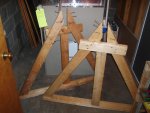
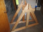
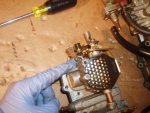
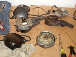
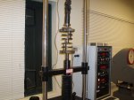
When I disassembled my motor, I used a motor stand similar to the one that is described in a sticky on the forums. I looked all over, but I can't find a picture of my stand. It was built of 2x4s and screws as well as a short piece of 2x12 for the "transom". Pretty simple. I also took the advice of somebody on here who said, "...build it twice as strong as you think it needs to be". I believe it was FR who said that. Well, I built it twice as strong as I thought it should be but it wasn't strong enough:( Obviously my original estimate wasn't good enough. Since I low-balled the estimate, I should have built it 4 times stronger than I thought it needed to be. I had to brace it a bit more due to the forces on it when I was removing some of the heavier bolts during disassembly.
 

yorab

Ensign
Joined
Jul 6, 2002
Messages
960
Re: 1963 75hp Starflite Rebuild

I used 4 new pistons and wrist pins, but the original connecting rods were still good so I had to separate them from the old pistons. I found that the automotive ball joint press worked well for that too. Keep in mind that driving out the wrist pins with a ball joint press WILL destroy your pistons, but if you're going to trash them anyway, who cares? This obviously won't work if you are going to reuse your pistons. I didn't dare use the ball joint press to press the new pins into the the new pistons; I used a suitable press. I'll get to that later when I start discussing assembly. If you don't have easy access to an arbor press, then the ball joint press can help for a few tasks.
 

Attachments

  • Rebuild 019.jpg
    Rebuild 019.jpg
    146.2 KB · Views: 0

yorab

Ensign
Joined
Jul 6, 2002
Messages
960
Re: 1963 75hp Starflite Rebuild

Here are a few pics of the stand that I built. I took it apart for storage purposes, but the the A-frame trusses are still intact. The crossmembers are not shown. I found out after some serious cranking on some stuck bolts that it needed to be stronger in the side-to-side manner. I slapped this stand together quickly it worked well after I reinforced it with more crossmembers.

There is a very nice tutorial for building a stand at http://forums.iboats.com/showthread.php?t=266570

dh4winn79 did a great job on his stand and the craftsmanship really shows through.
 

Attachments

  • LstMnt 001.jpg
    LstMnt 001.jpg
    142.4 KB · Views: 0
  • LstMnt 002.jpg
    LstMnt 002.jpg
    142.1 KB · Views: 0

yorab

Ensign
Joined
Jul 6, 2002
Messages
960
Re: 1963 75hp Starflite Rebuild

Here are some pics of the cylinder heads:
 

Attachments

  • LstMnt 003.jpg
    LstMnt 003.jpg
    147 KB · Views: 0
  • LstMnt 004.jpg
    LstMnt 004.jpg
    143.9 KB · Views: 0
  • LstMnt 006.jpg
    LstMnt 006.jpg
    147 KB · Views: 0
  • LstMnt 005.jpg
    LstMnt 005.jpg
    143.6 KB · Views: 0

yorab

Ensign
Joined
Jul 6, 2002
Messages
960
Re: 1963 75hp Starflite Rebuild

I also disassembled my carb. The carb from my parts motor was in better shape, so I used it. However, one or two of the screws that holds the throttle butterfly plates onto the rod had broken-off heads. The throttle rod does not normally need to be removed from the carb body when cleaning so I had trouble figuring out why the screw heads were broken off. I realized that the throttle return spring that keeps the butterflies in the closed position was broken. The PO must have been trying to remove the throttle rod in order to replace that spring.

If it does become necessary to remove the butterfly plate screws, the backside of the screw must be ground down first. This is because the backside is "staked" to prevent the screws from backing out and ending up in the combustion chamber.
 

Attachments

  • pic.JPG
    pic.JPG
    31.6 KB · Views: 1
  • Carb001.jpg
    Carb001.jpg
    136.6 KB · Views: 1
  • Carb002.jpg
    Carb002.jpg
    135.3 KB · Views: 1
  • Carb003.jpg
    Carb003.jpg
    133.7 KB · Views: 1
  • Carb004.jpg
    Carb004.jpg
    130.6 KB · Views: 1

yorab

Ensign
Joined
Jul 6, 2002
Messages
960
Re: 1963 75hp Starflite Rebuild

I also disassembled the starter to check out the condition of the interior. There were two models available for my engine and year: the Autolite and the Delco Remy. My starter was the Delco Remy. My commutator brushes were quite worn so I had to replace them. The first pic shows the worn brush next to a new one. You can do the most of the starter work yourself or you can take it to an alternator/starter repair shop. Starter rebuilds generally don't cost too much, but I like to do things on my own. It turns out that replacement brushes for the Autolite are much easier to install and are cheaper. The Delco Remy brushes for my model are harder to find and they need to be soldered into place. I took my starter to a local shop and the guy matched up a set of DR brushes for me. It cost about $15 for the set--much cheaper than OEM brushes. With a bit of advice from the forum, I was able to successfully solder in the new brushes. I also cleaned the commutator and bushing surfaces with emery cloth and cleaned out the inside of the starter body a bit in order to remove carbon that accumulates as the brushes wear.
 

Attachments

  • Brush001.jpg
    Brush001.jpg
    146 KB · Views: 0
  • Jan003.jpg
    Jan003.jpg
    147.9 KB · Views: 0
  • Jan012.jpg
    Jan012.jpg
    144.6 KB · Views: 0
  • Jan004.jpg
    Jan004.jpg
    147.8 KB · Views: 0
  • Jan005.jpg
    Jan005.jpg
    147.4 KB · Views: 0

yorab

Ensign
Joined
Jul 6, 2002
Messages
960
Re: 1963 75hp Starflite Rebuild

The distributor was disassembled next. I only had a few hours of operation on the cap before I started my rebuild, so I kept it. The contact points on the inside of the cap were in great shape. There was no wear from the rotor rubbing and there was no indication of arcing. I heard a slight bit of dryness or grinding when I rotated the rotor shaft by hand so I wanted to replace the bearings. This meant that I had to disassemble the distibutor assembly. Keep in mind that if the bearings are in good shape, then complete disassembly is not required.

I removed the breaker plate with the ignition components as well as the drive pulley. I then had to separate the distributor housing and sleeve from the bracket and bearing. This was easily accomplished by removing the retaining ring on the bottom of the sleeve. The cap on the bottom of the sleeve is some sort of plastic, so after so many years of use, it broke apart pretty easily. Don't remove it if you don't have to or else you will need to replace it. All in all, disassembly was fairly routine with the distibutor.

One thing that I did notice with my parts motor was that the distributor cam was cracked. You can see it if you zoom in on the upper left side of my first pic. I wonder if the PO knew about this. Perhaps this was the cause of him giving up on the motor and selling it for parts.
 

Attachments

  • Jan006.jpg
    Jan006.jpg
    142.6 KB · Views: 0
  • Jan008.jpg
    Jan008.jpg
    146.6 KB · Views: 0
  • Jan010.jpg
    Jan010.jpg
    131.1 KB · Views: 0
  • Jan007.jpg
    Jan007.jpg
    127 KB · Views: 0
  • Jan009.jpg
    Jan009.jpg
    147.6 KB · Views: 0

yorab

Ensign
Joined
Jul 6, 2002
Messages
960
Re: 1963 75hp Starflite Rebuild

I also disassembled the cowl. My original cowl is the blue/white one shown in the pic. My 1961 parts motor had a gray/white hood and is also shown in the pics. I actually like the side appliques on the 1961 parts motor better, so I decided to use the upper cowl from the 1961. The front and rear appliques that display the model (i.e. Starflite V) are attached to the lower cowl so I used my original 1963 lower cowl. These parts were completely interchangeable.

My FSM didn't have any information regarding the cowl, so I had to go blind. This wasn't much of a problem as there were no surprises in disassembling the cowl. First, the old deteriorating foam had to come out of the inside of the cowl. There are screws and u-clip type fasteners that secure the upper cowl to the bottom. There is also a rubber weatherstrip between the upper and lower sections.

The appliques are held on by a combination of concave plastic washers and plastic nuts in the inside of the cowl. One of the pics shows the nuts and washers. The plastic nuts were straightforward to remove. The appliques have studs that protrude through the cowl and the plastic washers fit onto those studs and hold at an area of the stud that has a smaller diameter. The washers are pretty tough to remove without breaking the applique studs. What I found to be best was to use a Dremel with a cut-off wheel. I cut through the washer near the base of the stud being very careful not to cut into the stud itself. I then popped off the washer with a screwdriver.
 

Attachments

  • Feb014.jpg
    Feb014.jpg
    140.4 KB · Views: 0
  • Feb016.jpg
    Feb016.jpg
    135.9 KB · Views: 0
  • Feb006.jpg
    Feb006.jpg
    141 KB · Views: 0
  • Feb007.jpg
    Feb007.jpg
    139.3 KB · Views: 0
  • Feb009.jpg
    Feb009.jpg
    148.5 KB · Views: 0

DargelJohn

Petty Officer 1st Class
Joined
Feb 14, 2010
Messages
337
Re: 1963 75hp Starflite Rebuild

Did you resurface the heads? I rebuilt a Johnson 88SPL last year and found the heads to be slightly warped. Used some sheets of 400 grit wet/dry paper on a flat surface and got my heads back to spec.

Great looking project you have here. I'm always looking for my next rebuild.
 

yorab

Ensign
Joined
Jul 6, 2002
Messages
960
Re: 1963 75hp Starflite Rebuild

DargelJohn, I had the shop surface the heads for me. I'll make the heads my first topic when I get to the re-assembly.
 

yorab

Ensign
Joined
Jul 6, 2002
Messages
960
Re: 1963 75hp Starflite Rebuild

Here are a few pics of the intake manifold with fuel pump attached. The exterior and interior are shown. Also shown is the reed box. Disassembly and inspection of these components was straightforward according to the instructions in the FSM.
 

Attachments

  • 006.jpg
    006.jpg
    138 KB · Views: 0
  • 007.jpg
    007.jpg
    137.2 KB · Views: 0
  • 008.jpg
    008.jpg
    130.5 KB · Views: 0
  • 009.jpg
    009.jpg
    131.7 KB · Views: 0
  • 011.jpg
    011.jpg
    145.3 KB · Views: 0

yorab

Ensign
Joined
Jul 6, 2002
Messages
960
Re: 1963 75hp Starflite Rebuild

So I guess that's about it for the disassembly of the motor. I tried to remember all the problems that I ran across but I'm sure I forgot something. After all, it did take years to get to this point. Of course, a complete rebuild can take as little as a few weeks if you have the time, money and a proper place to do the work.

I'll start posting pics dealing with the reassembly next. Although I have listed all of the disassembly steps first and then the reassembly will follow, it didn't actually work out like that. For instance, I had my gearcase completely torn down and rebuilt long before I even began to disassemble the disty, starter and cowl. But for the sake of having a more easy to follow thread, the disassembly comes before the reassembly.
 

yorab

Ensign
Joined
Jul 6, 2002
Messages
960
Re: 1963 75hp Starflite Rebuild

The first thing that I did after disassembly was to take my block to a local shop. The first shop that I chose is a very good automotive shop here in town but they couldn't help me with boring the block because their boring machine couldn't work on blind holes. Because of the cast shape of the block, the cylinder bores are essentially blind. I considered a marine shop, but the closest is about 50 miles away from me and they were a bit pricey. I finally found a guy near my town who mainly does automotive machining work, but his boring machine is able to bore blind holes. His prices were pretty good--much better than the marine shop.

He determined how much material would need to be removed to return the cylinders to a smooth, round condition. Based on his determination and the available oversized pistons, he had to bore 0.040" oversized. He also checked for flatness of the mating surfaces.

I also wanted him to clean up the block because I wanted to repaint. A thorough cleaning would remove the reddish colored paint on the interior of the block. Glyptal is a brand name of this special coating. The idea behind Glyptal is that it helps oil to flow more efficiently and it keeps any loose particles sealed to the interior walls. After researching the topic of Glyptal on this forum as well as some automotive and motorcycle forums, I found that some people out there swear by Glyptal and some people, even hotrodding veterans, say that the Glyptal doesn't help enough to justify the cost and time to apply it. I decided to go forward with the cleaning that would remove the coating. I also decided not to reapply the Glyptal. I usually don't go against what the OMC engineers thought was best, but I'm trying to have a good rebuild, not a perfect one.

I've attached some pics of the block before and after cleaing. I also have pics of the cleaned block next to my uncleaned spare block.
 

Attachments

  • P1010051.jpg
    P1010051.jpg
    151.4 KB · Views: 0
  • Picture3.jpg
    Picture3.jpg
    141.9 KB · Views: 0
  • Picture5.jpg
    Picture5.jpg
    144.6 KB · Views: 0
  • Picture4.jpg
    Picture4.jpg
    141 KB · Views: 0
  • Picture2.jpg
    Picture2.jpg
    146.1 KB · Views: 0

yorab

Ensign
Joined
Jul 6, 2002
Messages
960
Re: 1963 75hp Starflite Rebuild

and
 

Attachments

  • P1010143.jpg
    P1010143.jpg
    144 KB · Views: 0
  • Block03.jpg
    Block03.jpg
    141 KB · Views: 0
  • Block02.jpg
    Block02.jpg
    142.5 KB · Views: 0
  • Block01.jpg
    Block01.jpg
    144 KB · Views: 0
  • Block04.jpg
    Block04.jpg
    139 KB · Views: 0

yorab

Ensign
Joined
Jul 6, 2002
Messages
960
Re: 1963 75hp Starflite Rebuild

I took my heads to the local automotive machine shop that was unable to bore my block due to limitations of their machine. Even though they couldn't bore my block, they are a very capable bunch and I try to use them whenever I can. I had a total of 4 heads, 2 from my original motor and 2 from my parts motor. They looked over each and chose the best 2 heads to use. They cleaned the heads, checked for flatness and repaired the spark plug holes.

The two best heads needed helicoils in each spark plug hole because the threads were bad. They also milled the mating surfaces. The cost for everything was about $50.

Unfortunately, I don't have any pics of the heads after they came back from the shop.
 

Attachments

  • LstMnt 003.jpg
    LstMnt 003.jpg
    147 KB · Views: 0
  • LstMnt 006.jpg
    LstMnt 006.jpg
    147 KB · Views: 0

yorab

Ensign
Joined
Jul 6, 2002
Messages
960
Re: 1963 75hp Starflite Rebuild

I went a bit overboard with this project. I replaced every seal, gasket, bearing and critical nut and bolt throughout. I could have probably reused many of these components, but because the rebuild took so long, the pain of buying new parts was spread out over a very long time, so it wasn't too bad. Only a handful of parts are original such as the cast parts like the block, crankshaft, brackets, manifold, flywheel, etc. I also did a LOT of internet searching and found some really good deals.

I had to decide what to do about fasteners. OEM fasteners would have cost a thousand dollars. That was out of the question, though I did buy a few unique OMC fasteners. The original fasteners on my motor were not rusted even after 48 years. Some bolt heads were painted, but most were exposed since the paint was long gone. I wondered what material would not rust after all that time. I found out that the original fasteners had cadmium in them or plated on them. Of course, cadmium is toxic so it's not used in fasteners these days. Many people say to use steel, but I didn't want to put a lot of time into the rebuild just to have rusty bolt heads after one season. I wanted stainless steel for it's open-air corrosion resistance. This would prevent rusty bolt heads. However, the aluminum block and the stainless fasteners have very different electronegativities, so they are far apart on the galvanic scale. Corrosion at the threads is a good possibility. I decided to use stainless fasteners with a marine-grade anti-sieze from Loctite. The Loctite stuff is meant to prevent the galvanic corrosion between dissimilar metals. I don't know for sure if this was the correct thing to do, but I'll find out with time.
 

yorab

Ensign
Joined
Jul 6, 2002
Messages
960
Re: 1963 75hp Starflite Rebuild

The crankshaft checked out okay, so I reused it. I replaced the crankcase seal rings that fit into a groove on the crankshaft webs as well as the crankcase head seal rings and gasket. I replaced the bearings using a nifty tensile tester that I had access to at school. It's typically used to pull materials but it can compress as well. With an assortment of sockets and pipe sections, I was able to press nearly all of the seals and bearings on my motor. I've attached some pics of the upper and lower bearings being pressed into place.
 

Attachments

  • P1010133.jpg
    P1010133.jpg
    147.5 KB · Views: 0
  • P1010134.jpg
    P1010134.jpg
    142.7 KB · Views: 0
  • P1010135.jpg
    P1010135.jpg
    136 KB · Views: 0
  • P1010136.jpg
    P1010136.jpg
    140.6 KB · Views: 0
  • P1010144.jpg
    P1010144.jpg
    144.5 KB · Views: 0

yorab

Ensign
Joined
Jul 6, 2002
Messages
960
Re: 1963 75hp Starflite Rebuild

I drove the piston wrist pins in with a rubber mallet since I didn't have an appropriate piston cradle. First, I put the pins in the freezer overnight. The next day I put the pistons in boiling water for about 15 minutes. The expansion of the pistons and the contraction of the pins was enough that I could lay the piston in my lap and tap in the pins with the mallet. I avoided laying the piston on a hard surface because I didn't want to knock the piston out of round. I put in new wrist pin bearing and I reused my connecting rods. Once the pins were in far enough I installed new circlips that came with the pistons.

It is critical that the wrist pin be driven in from the side that has the word "LOOSE" cast into it if you are using a press. I'm not sure if it matters if you use the laptop method that I used. If you are using a press and you drive the pin in too far, you must continue to drive the pin completely out and start again from the side marked "LOOSE". You cannot simply back the pin up. You will damage the piston if you try because the tight side will be unsupported by the press. It took me a while to get my brain wrapped around the reason why, but some knowledgeable folks on the forum explained it to me well.

Also, it's important that the oil holes in the connecting rod are facing upward when the block is reassembled. This means that two of the connecting rods must be connected to the pistons one way and the other two should be connected the opposite way. To illustrate, if you zoom in on my pic near the wrist pin bearings, you can see the oil hole is upward for each of my connecting rods yet two piston deflectors face left and two face right. Don't focus on the cast-in part numbers because the oil holes must have been drilled into a random side of the rod.
 

Attachments

  • P1010137.jpg
    P1010137.jpg
    146.2 KB · Views: 0
  • P1010141.jpg
    P1010141.jpg
    146 KB · Views: 0

yorab

Ensign
Joined
Jul 6, 2002
Messages
960
Re: 1963 75hp Starflite Rebuild

Ya gotta love the Seloc manual. So many ridiculous words of wisdom in there:) Here's what it says about the laptop method:

"Now, assume a sitting position and lay a couple towels over your lap. Hold your legs tightly together to form a cradle for the piston above your knees...Use sharp hard blows with a hammer. Your legs will absorb the shock without damaging the piston. If this method is used on a regular basis during the busy season, your legs will develp black-and-blue areas, but no problem, the marks will disappear in a few days."

Whew, I'm glad that Seloc can make good medical diagnoses as I thought the black and blue marks would never go away;)
 

yorab

Ensign
Joined
Jul 6, 2002
Messages
960
Re: 1963 75hp Starflite Rebuild

Next, I inserted the pistons into the cylinders and connected the rods to the crankshaft journals. The service manuals say to avoid using automotive type ring compressors because the notches in the rings must be aligned with the locating dowels and must remain that way during and after insertion of the pistons. Supposedly, it's harder to tell whether the notches remain aligned when using the automotive compressors. However, I read opinions from people who have installed hundreds or even thousands of rings with the automotive ring compressors.

I went with the automotive type. I inserted the piston just until the first ring was inside the cylinder bore. I then removed the compressor and looked to be sure that the notches were aligned with the dowel. This was possible to see since the cylinder bore is beveled. Then I used the compressor again for the next ring in the same manner.

Then I connected the connecting rods to the crankshaft using some grease to help hold the rod needle bearings in place until the rod caps were installed. I used new connecting rod bolts and I made sure that the caps were perfectly aligned with the rod by running a pick tool over the joint and making sure that I could not feel a raised ridge, indicating that the cap was not in place.

Finally, I placed the spaghetti seal into the groove in the crankcase mating surface using Scotchweld 847 and bolted the crankcase to the cylinder block.
 

Attachments

  • P1010144.jpg
    P1010144.jpg
    144.5 KB · Views: 0
  • P1010142.jpg
    P1010142.jpg
    143.9 KB · Views: 0
  • P1010145.jpg
    P1010145.jpg
    143 KB · Views: 0
  • P1010146.jpg
    P1010146.jpg
    143.1 KB · Views: 0
Top