Fuel pump no power/ relay to pump help

flyhigh123

Petty Officer 2nd Class
Joined
Nov 17, 2012
Messages
112
Took boat out and fuel pump not getting power when key turned to on position. Engine is Volvo gas dp 7.4gl.

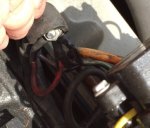
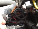
I made a mistake when diagnosing my fuel pump and removed the relay and mixed up the wiring.

1st can someone please advise me on the proper relay wiring!

I have 4 cables that ran to the relay: 12v red power
Ground
Yellow power to fuel pump
Yellow/orange cable( I assume this is from the ignition)

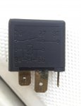
The relay is a 30amp and has the following marks: 30,85,86,87,87a

Can someone please advised which color to which number? Reason I ask is I swear I tried every combo.

I know the pump works as direct power to pump powers it.

When the key is in the on position, is the yellow/orange cable suppose to read 12v?

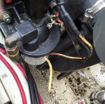
I took a look under the ignition and there is a purple cable. Was hoping to see the yellow/orange cable but that wasn't there. I can't follow the yellow orange cable as its all wrapped up after the relay.

To better understand my engine, does the ignition power go to ecm which then goes to fuel pump or does the ignition go direct to fuel pump relay?
 

Attachments

  • image.jpeg
    image.jpeg
    126.4 KB · Views: 3
Last edited:

flyhigh123

Petty Officer 2nd Class
Joined
Nov 17, 2012
Messages
112
Here is another picture
 

Attachments

  • 630240d1458427247-help-fuel-pump-not-getting-power-relay-help-image.jpg
    630240d1458427247-help-fuel-pump-not-getting-power-relay-help-image.jpg
    355.5 KB · Views: 3

Fun Times

Moderator
Staff member
Joined
May 16, 2009
Messages
9,014
Engine is Volvo gas dp 7.4gl.
Is the last letters of the engine size Gi or GL?
Does the ignition power go to ecm which then goes to fuel pump or does the ignition go direct to fuel pump relay?
The reason we need to know is because GL = a carbureted engine while Gi = Fuel injected. From your photos, it appears you have a carbureted engine but mentioned ECM like a fuel injection system would utilize.

What year is the engine/boat?
Also after the GL or Gi, there should/may be some other letters after the GL such as 7.4GLPLKD for example. Knowing that info should help some too.

1st can someone please advise me on the proper relay wiring!

I have 4 cables that ran to the relay:
12v red power
Ground
Yellow power to fuel pump
Yellow/orange cable( I assume this is from the ignition)

When the key is in the on position, is the yellow/orange cable suppose to read 12v?

Does the ignition power go to ecm which then goes to fuel pump or does the ignition go direct to fuel pump relay?
First if it is a carbureted engine like I believe it is, The fuel pump won't just turn on when you turn the key to the first on/ignition position. The pump should power up as soon as you start cranking the engine over to start because the yellow/Red (not orange) wire you see at the key switch is for the cranking system so the yellow/red will only have 12v power when you turn the key to start.... Then starting/cranking power goes/turns off when you release the key to on/run. The purple wire at the key keeps the ignition system & dash gauges powered up but not necessarily the fuel pump directly. Once the engine is running, the signal to operate/trigger the fuel pump comes from the alternator via the green wire shown in your attached photos that you didn't mention earlier;)....Also seen in the diagram below.

Now if the engine is fuel injected then the fuel pump turns on then runs in a different way vs the carb system.

Below "should" be a diagram that you can follow.
Again, Bear in mind that you didn't mention a green wire above that you do appear to have.

Also try checking the green wire for continuity like this guy had to. I believe there is a diode in the system to help avoid power back feed.
http://forums.iboats.com/forum/engi...-fuel-pump-wiring-issue?p=5310580#post5310580

2013-05-14_043617_scan0002.jpg
 
Last edited:

flyhigh123

Petty Officer 2nd Class
Joined
Nov 17, 2012
Messages
112
Thanks for the reply. The engine is carbureted. I may have misued the word ecm. I'm the 2nd owner of this boat. It's a 97. I said ecm as there is a small electronic box at the top upper right of the engine with many wires going into it.

Previously, when I turned the key to on position I would be able to hear the fuel pump running. Whether or not that is correctly wired I am not sure as the previous owner may have done work on it.

For the green, the yellow cable that is paired with the orange, the yellow portion has a green stripe in it.

Thanks for the help! Learning about this engine is a process.
 
Last edited:

flyhigh123

Petty Officer 2nd Class
Joined
Nov 17, 2012
Messages
112
Fun times: in the relay picture j posted above, does that match your diagram? Another person told me that the relay I posted would be flipped compared to your diagram for 85 and 86. Meaning 85 is ground and 86 ignition?
 

Fun Times

Moderator
Staff member
Joined
May 16, 2009
Messages
9,014
Fun times: in the relay picture j posted above, does that match your diagram? Another person told me that the relay I posted would be flipped compared to your diagram for 85 and 86. Meaning 85 is ground and 86 ignition?
Glad someone caught that as I meant to address that last night/morning too.:sleeping:
You mean 85 should be power and 86 should be ground as the diagram above is reversed for the fuel pump relay.

85 & 86 do need to be turned around in that diagram. I pulled that one off the internet as it's easier to copy and paste plus it seemed to cover a wide rang of years. Unfortunately some service manuals do tend to be inaccurate at times making it difficult. Knowing you have a 1997 Carbureted engine helps a little. Some of your model numbers after the 7.4GL could be either LK or BY.

You'll need to read pages 9-10, http://boatinfo.no/lib/volvo/manuals/lk_elect.html#/172
And page 9-11 on the right. Both covers the 7.4GL engine model. http://boatinfo.no/lib/volvo/manuals/lk_elect.html#/174

Also just so your aware, that box with the wires is a electronic engine management module that could put the boat in slow mode should the engine overheat or lose oil PSI.

I'm not great with computers, Anyone here know how to change that diagram above so it reads correctly? Or make a note in red to swap 85 & 86 around and post it...Thanks.
 

bruceb58

Supreme Mariner
Joined
Mar 5, 2006
Messages
30,530
The fuel pump should not turn on with the ignition turned on.

The diagram that FunTimes posted looks like it came from a Seloc manual which explains why it is not correct.

2012-06-22_154617_volvo_fuel_pump_circuit_96.jpg
 
Last edited:

Fun Times

Moderator
Staff member
Joined
May 16, 2009
Messages
9,014
The fuel pump should not turn on with the ignition turned on.

The diagram that FunTimes posted looks like it came from a Seloc manual which explains why it is not correct.
Thanks Bruce.

Looking at the manual I just posted, if you read all of the Carbureted engines at the fuel pump relay, though they are very hard to see/read but some appear correct while others seem to read in reveres for the 85 and 86 electrical circuits such as the 5.7GL on page 9-7 for one example.

I'd say that if the fuel pump did power up when the key was turned on but not in cranking mode, than one or possibly two of the inline diodes are bad allowing power to back feed/flow somewhere along the line.
 

bruceb58

Supreme Mariner
Joined
Mar 5, 2006
Messages
30,530
If you think about it, the only way the fuel pump would turn on when when you turned on the key is if there was a miswire at the alternator with the green wire hooked up to the excite wire or the alternator is driving the green wire with the alternator not outputting.

As far as 85/86 swapped, it really doesn't matter since that is just the coil connections of the relay.

I have an OEM paper LK manual at home. I will look at it later tonight.
 
Last edited:

Fun Times

Moderator
Staff member
Joined
May 16, 2009
Messages
9,014
Question for you because I don't know. Should the 85 and 86 be crossed over, due to the design of the relay workings... could swapping the two numbers around power up the fuel pump when keyed on engine off? I think I'm asking because of the two number below showing 85 - and 86 + for the coil and maybe confusing me somehow.
https://en.wikipedia.org/wiki/DIN_72552
85relay coil -
86relay coil +
Relay
 

bruceb58

Supreme Mariner
Joined
Mar 5, 2006
Messages
30,530
Wouldn't matter unless there was a back EMF diode in the relay which is doubtful. Do a google search and you will see them wired with both polarities.
 
Last edited:

Fun Times

Moderator
Staff member
Joined
May 16, 2009
Messages
9,014
Do a google search and you will see them wired with both polarities.
I had done that at one point and that was another reason I was questioning the connections in my mind. Thanks again Bruce.:)
 

bruceb58

Supreme Mariner
Joined
Mar 5, 2006
Messages
30,530
I just confirmed that pin 86 is indeed the ground. Even with an OEM manual it is tough to read.
 

flyhigh123

Petty Officer 2nd Class
Joined
Nov 17, 2012
Messages
112
If everything was wired up correctly, if I metered the fuel pump when cranking it should read 12v correct? I'll take a look tomorrow and try what was suggested. I will also meter the green wire at the alternator and check the ohms from on end to the other. I tried to look for the orange cable at the other end but have not found it yet. The diagram says it goes to starter relay. Need to find that relay and can check.

The fuel pump works when jumped but otherwise not.
 

flyhigh123

Petty Officer 2nd Class
Joined
Nov 17, 2012
Messages
112
Also here is a picture of a few wires all wired together. Does this look right? This may be part of the problem. This group of wires was sitting behind the alternator. The green wire is the one going to the fuel pump.

It seems weird that there are 4-5 wires connected with a nut and bolt sitting behind the alternator when on the diagram the green wire goes directly to the alternator. The diagram above shows the green connecting to the back of the alternator but how do I identify which connector on the back of the alternator?


I'll try to list the colors.
I may be finding another wiring issue.
 

Attachments

  • image.jpeg
    image.jpeg
    37.1 KB · Views: 1
  • image.jpeg
    image.jpeg
    118.1 KB · Views: 1
Last edited:

bruceb58

Supreme Mariner
Joined
Mar 5, 2006
Messages
30,530
Seriously? Someone connected all those together?

It should go to the L2 terminal.
 
Last edited:

flyhigh123

Petty Officer 2nd Class
Joined
Nov 17, 2012
Messages
112
Seriously? Someone connected all those together?

It should go to the L2 terminal.
Yah. It looks like a lazy man's way of doing something. All connected together with electrical tape wrapped around and what looked liked a spark plug wire cover around the nut. I'm going to take a picture of the alternator back and the wiring going in to figure out where the rest of those wires are coming from/ going to. The previous owner may have replaced the alternator and maybe took the easy way out.
 

Fun Times

Moderator
Staff member
Joined
May 16, 2009
Messages
9,014
If everything was wired up correctly, if I metered the fuel pump when cranking it should read 12v correct?
And working correctly than yes the pump end should have around 12 volts while cranking.....Then the green wire from the alternator is supposed to power the pump once running.

I'll take a look tomorrow and try what was suggested. I will also meter the green wire at the alternator and check the ohms from on end to the other.
Yes after the discussion about the alternator, if possible, try testing for power both at the alternator stud of the green wire with the key off, key on and key cranking the engine over then do the same at the green wire at the relay end and if willing, post your findings as it would be helpful & interesting.
Also wondering if you wouldn't mind posting what the ohms readings you get while testing the green wire. Since the green wire has a diode, Sometimes you'll get two readings if you test the wire in both directions by swapping/reversing the multimeter leads around....Thanks.

I tried to look for the orange cable at the other end but have not found it yet. The diagram says it goes to starter relay. Need to find that relay and can check.
The starter relay that runs to the fuel pump relay will be Yellow/Red. The wire turns to Orange as it gets closer to the Fuel pump relay.


^ Oh, So much for everything wired up correctly.:( Hope you can figure it out without much headache.
 
Last edited:

flyhigh123

Petty Officer 2nd Class
Joined
Nov 17, 2012
Messages
112
The manual states there are 2 circuit breakers for fuel pump, one on green and one o orange wire. Any idea where these circuit breakers might be located and how they look? Is that just another name for the diode?

Also the manual states there is a 20 amp fuse from the ignition. It states it should be somewhere near the dash. Any idea how this fuse looks?

At least i'm learning a ton about engines.
 
Last edited:
Top