Wiring diagram for 3.0 mercruiser

grizzreaper

Petty Officer 2nd Class
Joined
Oct 8, 2007
Messages
160
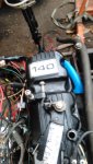
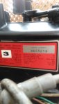
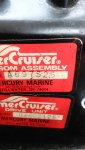
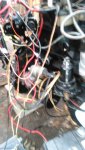
Ok I been looking all over .I have tried different sites and Google.i took a donor block and took my valve cover, flywheel, carb,manifold, rear engine mount,coupler, fuel pump and igntion coil. Going to pull my cap and rotor next.i tried wiring it up but it just won't turn over.i have power to starter and if I jump the starter it will turn over. now I have the original wire harness and I have taken a 12 volt battery n checked each wire. It goes #1 black ground, #2 is gray wire and spliced twice, #3 is a brown wire, no #4 wire but there is a hole, #5 is a purple wire spliced 4 times, #6 big red wire with a purple/black stripe and spliced three times, #7 is a yellow wire with a red stripe, #8 is a light blue wire, and #10 is a black wire with a white stripe with plastic block screwed into. Sorry for the long post but I want to put the motor back in but I want to make sure it's good to go. Thanks in advance.posted a couple of pics with serial numbers on valve cover.
 

Attachments

  • photo306089.jpg
    photo306089.jpg
    1.3 MB · Views: 14
  • photo306090.jpg
    photo306090.jpg
    1 MB · Views: 8
  • photo306091.jpg
    photo306091.jpg
    1.1 MB · Views: 13
  • photo306092.jpg
    photo306092.jpg
    1.4 MB · Views: 16

Scott Danforth

Grumpy Vintage Moderator still playing with boats
Staff member
Joined
Jul 23, 2011
Messages
47,296
BTW...the Factory manual has the schematic
 

grizzreaper

Petty Officer 2nd Class
Joined
Oct 8, 2007
Messages
160
I don't have a manual for it. Everything I have done is by trial n error or Google. What I am trying to get is to start the motor and then check the compression before I put the motor back in the boat.
 

achris

More fish than mountain goat
Joined
May 19, 2004
Messages
27,468
To power the 'ignition' side, connect a wire between pins 6 (red/pur, POWER) and 5 (pur, IGN). That powers up the ignition circuits. To crank the engine, short the power pin (6) to the START pin, 7 (red/yel). That will crank the engine. Once it's running, remove the 6 to 7 wire. To stop the engine, remove the 6 to 5 wire. To crank without spark (for compression test), just short 6 to 7, without the 6 to 5 wire in place. Don't forget to supply cooling water to the engine while running it. ;)

Chris..........
 

grizzreaper

Petty Officer 2nd Class
Joined
Oct 8, 2007
Messages
160
Would anyone know why the pervious owner would of splice the purple wire 4xs . I see the choke, alternator and igntion coil. That's three . Any idea why there is 4 .
 

grizzreaper

Petty Officer 2nd Class
Joined
Oct 8, 2007
Messages
160
No idea .this is all Greek to me. I am way out of my realm here. I have tripled check each wire and everything is spliced with right color of wires except the purple one. Wasn't for all of you on here n Google I be up a creek lol .
 

achris

More fish than mountain goat
Joined
May 19, 2004
Messages
27,468
If you have 4 purple wires spliced together, and one goes to the coil, one goes to the alternator and one goes to the choke, the 4th MUST be FROM the battery (via the key of course)... That's how electricity works....

Chris....
 

achris

More fish than mountain goat
Joined
May 19, 2004
Messages
27,468
Took the time and coloured the wiring diagram for you. Might make it a bit easier to follow. Notice the splice point on the purple, 4 wires.... ;)

140ign.JPG

Chris........
 

grizzreaper

Petty Officer 2nd Class
Joined
Oct 8, 2007
Messages
160
Ah yes .thank you very . Your the best .I have the harness in my hand n there is a purple yellow wire. Thanks again everyone for all your help. Happy new year to all
 

grizzreaper

Petty Officer 2nd Class
Joined
Oct 8, 2007
Messages
160
Would anyone have the diagram for the cluster wiring. I have the harness now wired as per this diagram. Thanks in advance.
 

achris

More fish than mountain goat
Joined
May 19, 2004
Messages
27,468
Thanks so much specially for taking the time to color code it.

If you keep it quiet, I'll tell you a secret... I coloured that diagram months ago. I have it and the trim diagram printed on one side of an A3 sheet, and on the other side, the engine wiring diagram... I laminated it, and it lives in my boat....

Chris...........

Oh, and my engine wiring....
MPI-V6.png
 

grizzreaper

Petty Officer 2nd Class
Joined
Oct 8, 2007
Messages
160
Ok since you have help me out with the other wiring lol. I also printed them n laminated. My trim motor was not working right. So I Jimmy rigged some 60 amp push buttons , in it works. Since I have a newish shifter to put in how do I wire the trim motor to the buttons on the lever. I have pulled n cut all the old harness out. I also need to know where the trim tab connectors go back on the motor. Thanks in advance. Just think soon I will be able to answer ?'s on here lol
 

achris

More fish than mountain goat
Joined
May 19, 2004
Messages
27,468
OK, by the serial numbers you SHOULD have a twin solenoid trim pump assembly. If you don't, if it's single solenoid, let me know and I'll mash up a drawing for you.... Here's a standard twin solenoid, with control lever trim switches setup wiring diagram....

Chris........

powertrim.PNG
 

grizzreaper

Petty Officer 2nd Class
Joined
Oct 8, 2007
Messages
160
Thanks again Chris. So neither of the senders connect to the terminals on the motor
 
Top