Where do I belong? Alum Goods 1687, SS16 Clone?

renns

Petty Officer 1st Class
Joined
Dec 20, 2017
Messages
316
1975 SuperSport 16'
Negatory on my own upholstery work. I removed the original fixed seats (1/2" ply w/ a vinyl cover riveted directly the bow interior structure), cut new boards of the same size/shape, and had those upholstered along with the vertical cushions directly below the windshield. $500 materials and labor (2019 prices).
Thx for info. Will try putting together something similar.
 

renns

Petty Officer 1st Class
Joined
Dec 20, 2017
Messages
316
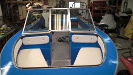
Quick update - two side cushions for the bow are complete. We used the almost-no-sewing option, with top panel folding over each of the sides. Just the corner edges needed stitching. I was going to try stitching covers with nice piping on the edges, but April is not the time to learn yet another trade. I was hoping to convince the admiral to pick a colour other than white, but no go. Need to scrounge a triangle piece of 3/8 ply to finish the bow cushion, but at the current price I'm waiting to see if I run across the required scrap somewhere in the next few weeks.
WP_20220412_16_15_39_Pro.jpg
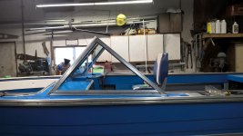
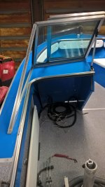
The replacement windscreen is now fitted and mounted to the boat. The original has crazed plastic panels, and was missing the center hinged portion. The replacement I bought second-hand was from some fiberglass boat, but the width matched. What a big job that was, trying to fiddle it around to get it to fit, while protecting the fresh paint on the consoles and gunnels. Alignment was quite tricky to get the center glass to close properly. I didn't like the very swept back angle discussed a page or two back, so I disassembled the side 'triangles', removed the tempered glass, and modified them to push the windscreen back closer to the original angle. This worked nicely in that the top now sits about 19-1/2" above the console, almost 4" higher than the original, and looks a little more substantial. I know there's no way the old mooring cover will fit without extensive modification, but I figured it was worth the trade-off.
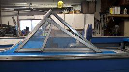
Here's a pic with the original side glass up against the new version.
WP_20220412_16_14_05_Pro.jpg
With the tempered glass panels from the side triangles now removed, I plan to replace with plexiglass. I might add a vertical support mid-way along, and to break that triangle into a trapezoid and triangle, and leave the triangle open like I see on the Starcrafts. That would give a handy grab point for entry/exit, while the short side windows would hopefully still provide some protection from buffeting when at speed.
WP_20220412_16_14_21_Pro.jpg
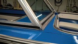
The bottom of this new windscreen must have fit in a molded channel on the fiberglass hull, as the bottom didn't sit flat against the consoles. I used some old aluminum angle and with a bit of fiddling was able to box in the gap area at the bottom. That aluminum is left bare, but will get the Sharkhide treatment to hopefully keep it looking fresh.

WP_20220412_17_10_14_Pro.jpg


WP_20220412_16_21_28_Pro.jpg

Next up is wiring, then re-hang the Yamaha, and start thinking about getting wet!
 

ShoestringMariner

Lieutenant Commander
Joined
Apr 18, 2015
Messages
1,602
Quick update - two side cushions for the bow are complete. We used the almost-no-sewing option, with top panel folding over each of the sides. Just the corner edges needed stitching. I was going to try stitching covers with nice piping on the edges, but April is not the time to learn yet another trade. I was hoping to convince the admiral to pick a colour other than white, but no go. Need to scrounge a triangle piece of 3/8 ply to finish the bow cushion, but at the current price I'm waiting to see if I run across the required scrap somewhere in the next few weeks.
View attachment 358736
The replacement windscreen is now fitted and mounted to the boat. The original has crazed plastic panels, and was missing the center hinged portion. The replacement I bought second-hand was from some fiberglass boat, but the width matched. What a big job that was, trying to fiddle it around to get it to fit, while protecting the fresh paint on the consoles and gunnels. Alignment was quite tricky to get the center glass to close properly. I didn't like the very swept back angle discussed a page or two back, so I disassembled the side 'triangles', removed the tempered glass, and modified them to push the windscreen back closer to the original angle. This worked nicely in that the top now sits about 19-1/2" above the console, almost 4" higher than the original, and looks a little more substantial. I know there's no way the old mooring cover will fit without extensive modification, but I figured it was worth the trade-off.
Here's a pic with the original side glass up against the new version.
View attachment 358734
With the tempered glass panels from the side triangles now removed, I plan to replace with plexiglass. I might add a vertical support mid-way along, and to break that triangle into a trapezoid and triangle, and leave the triangle open like I see on the Starcrafts. That would give a handy grab point for entry/exit, while the short side windows would hopefully still provide some protection from buffeting when at speed.
View attachment 358735
The bottom of this new windscreen must have fit in a molded channel on the fiberglass hull, as the bottom didn't sit flat against the consoles. I used some old aluminum angle and with a bit of fiddling was able to box in the gap area at the bottom. That aluminum is left bare, but will get the Sharkhide treatment to hopefully keep it looking fresh.

View attachment 358738


View attachment 358737

Next up is wiring, then re-hang the Yamaha, and start thinking about getting wet!
Looking awesome!! That boat is looking just killer. I like the bigger windshield.
 

renns

Petty Officer 1st Class
Joined
Dec 20, 2017
Messages
316
Looking awesome!! That boat is looking just killer. I like the bigger windshield.
Thanks. It is certainly more enjoyable putting stuff in/on the boat for good, rather than taking stuff off! Paint looks nice from a distance. There's orange peel and dust in the finish in spots. I did the wet sand/polish/wax on one side of the hull, and it turned out nice. Waiting for a nice weather day when I'm not working to get the boat outside for the rest of that work.
 

renns

Petty Officer 1st Class
Joined
Dec 20, 2017
Messages
316
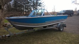
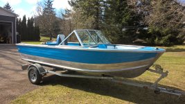
She sees daylight, even if only for a few hours! Needed access to the shop for vehicle maintenance. I'm very happy with how the taller windshield worked out - more substantial-looking than the original.
 

Attachments

  • WP_20220414_15_52_58_Pro.jpg
    WP_20220414_15_52_58_Pro.jpg
    1.9 MB · Views: 20
  • WP_20220414_15_52_40_Pro.jpg
    WP_20220414_15_52_40_Pro.jpg
    2.4 MB · Views: 20

renns

Petty Officer 1st Class
Joined
Dec 20, 2017
Messages
316
Sharkhide isn't on yet. Still needs final wet-sanding below the blue, and then application of the SharkHide. I ended up buying direct from the Sharkhide site, and having it shipped in. I have applied it to rubrails, and a few smaller parts. No experience on big panels yet.
 

classiccat

"Captain" + Starmada Splash Of The Year 2020
Joined
Dec 20, 2010
Messages
3,412
getting her some vitamin-D.

Lookin' sharp there @renns ! the new windscreen looks right at home.
 

ShoestringMariner

Lieutenant Commander
Joined
Apr 18, 2015
Messages
1,602
Hey, How did you find the 1/8” thick butyl tape to be in terms of compressibility? I’m debating whether to pick up 1/16th But I figure there’s not enough build there, especially under the windshield.
 

renns

Petty Officer 1st Class
Joined
Dec 20, 2017
Messages
316
It worked out OK, with a bit of 'squeeze-out' when the mount screws were tightened. I've got lots left of my roll if you want it - 1/8" x 3/4".
 

renns

Petty Officer 1st Class
Joined
Dec 20, 2017
Messages
316
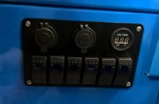
Some wiring done, switch panel mount sorted out. Found out the ebay switch panel isn't great quality. A few of the male spade connectors on the back of the switches popped right off when I went to re-wire them. That required switch disassembly, and careful soldering of the backside of the spade into the rocker receptacle inside the switch body. All work well now, but I'm thinking I probably should have done the whole lot of 6, rather than just the three that broke.
1650582748378.jpeg

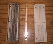
Also, we wanted to keep the original step pad, or something similar, on the gunnel tops to protect the paint when climbing in and out of the bow. The originals were very discoloured and grimy. Boiling in a mix of water/vinegar did very little to clean them up. Then I added some random kitchen cleaning product with bleach, and BAM, they came out looking new! These are held down with two aluminums strips (one shown between the fore and after samples).
1650580295802.jpeg

I'm off to cabin up north for the weekend, so no boat work, and falling further behind on yard work. Ah well...
 
Last edited:

ShoestringMariner

Lieutenant Commander
Joined
Apr 18, 2015
Messages
1,602
Some wiring done, switch panel mount sorted out. Found out the ebay switch panel isn't great quality. A few of the male spade connectors on the back of the switches popped right off when I went to re-wire them. That required switch disassembly, and careful soldering of the backside of the spade into the rocker receptacle inside the switch body. All work well now, but I'm thinking I probably should have done the whole lot of 6, rather than just the three that broke.
View attachment 359177

Also, we wanted to keep the original step pad, or something similar, on the gunnel tops to protect the paint when climbing in and out of the bow. The originals were very discoloured and grimy. Boiling in a mix of water/vinegar did very little to clean them up. Then I added some random kitchen cleaning product with bleach, and BAM, they came out looking new! These are held down with two aluminums strips (one shown between the fore and after samples).
View attachment 359175

I'm off to cabin up north for the weekend, so no boat work, and falling further behind on yard work. Ah well...
Those step plates came out beautifully. Bummer about the switch panel, I bought the same one too. Blue sea or sea dog brand or something?
 

renns

Petty Officer 1st Class
Joined
Dec 20, 2017
Messages
316
Not sure of the brand. It's definitely fait en Chine. I'd give those terminals a wiggle before installation. Two of mine popped with very light touch. The other, well, I might have been a bit ham-fisted with the removal of the pre-wired section.
 

renns

Petty Officer 1st Class
Joined
Dec 20, 2017
Messages
316
More progress made last couple evenings:

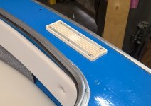
1.) Step pads from a couple posts ago are now installed just forward of the windscreen.
2.) Yamaha F60 hung back on the transom, after a 6 month hiatus on the engine stand. I buttered in the inside surfaces of the holes, as well as the bolts and washer with lots of 5200. Excess squeeze-out on the visible areas was cleaned up with acetone.
3.) 3/8" ply kick panels fabricated to trim out inside of hull in console area. I'm low on Nautolex, or I'd have just wrapped these. They are now getting painted instead. Starboard side will include a pass-through for wiring to the fuse-panel that will be mounted on that panel.
4.) Battery box has been hacked to include a high current fuse and battery disconnect switch.
5.) Custom harness for tachometer and trim meter. Neither were in the boat when I got it. Here's hoping they work!
6.) Transom drilled through for transducer harness pass-through. It was drilled a bit oversized, and the inside liberally coated with G-Flex epoxy.

Next up is installing the kick panels, pulling the transducer wire through my braided harness, and getting on with the remaining wiring. Audio system and interior lights will wait until post-splash.

I bought a used prop for the Yamaha, one step coarser pitch as the current prop allowed the motor to overspeed when lightly loaded on a cool fall day. That was noticed due to rev limiter kicking in, as we didn't have a tach at the time. This prop, a Quicksilver, has the correct hub/spline setup for the Yamaha, but didn't come with the thrust washer. Using the original Yamaha washer isn't an option, as a thicker one is needed to keep this prop from rubbing on the lower unit. Live and learn...
Pics tomorrow!
 

renns

Petty Officer 1st Class
Joined
Dec 20, 2017
Messages
316
Pics finally sync'd from the phone.
Nice and clean step pads.
1651073868542.jpeg
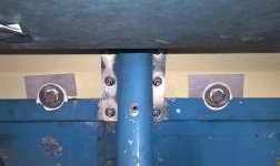
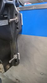
Lower motor mount bolts passed through edge of transom tray. Here's a shot of the spacers I made up to side on the top lip, keeping the transom bolt and washer properly aligned.
1651073259556.jpeg
1651073340267.jpeg
More aluminum spacers were made up to shim the motor back from the transom skin slightly to prevent the top of the transom clamp from fouling on the transom cap.
1651073920566.jpeg
 

renns

Petty Officer 1st Class
Joined
Dec 20, 2017
Messages
316
Now that they are installed, what's the preferred method to install transom clamp bolts? I buttered everything up with 5200, and snugged the bolts up, but not fully torqued. My thought is that will leave a thicker layer of the 5200 to cure under the washers. Tonight, 24 hrs later, I'm planning to torque to spec, and add the jam nuts to each.
 

ShoestringMariner

Lieutenant Commander
Joined
Apr 18, 2015
Messages
1,602
Now that they are installed, what's the preferred method to install transom clamp bolts? I buttered everything up with 5200, and snugged the bolts up, but not fully torqued. My thought is that will leave a thicker layer of the 5200 to cure under the washers. Tonight, 24 hrs later, I'm planning to torque to spec, and add the jam nuts to each.
I don’t know about the required torque specs but I’d use Nylock nuts. Not compression nuts though. Stainless threads can be nasty for galling and seizing. I never use impact guns on stainless hardware either
 

ShoestringMariner

Lieutenant Commander
Joined
Apr 18, 2015
Messages
1,602
Pics finally sync'd from the phone.
Nice and clean step pads.
View attachment 359540
Lower motor mount bolts passed through edge of transom tray. Here's a shot of the spacers I made up to side on the top lip, keeping the transom bolt and washer properly aligned.
View attachment 359538
View attachment 359539
More aluminum spacers were made up to shim the motor back from the transom skin slightly to prevent the top of the transom clamp from fouling on the transom cap.
View attachment 359541
Nice work! (y) :)
+1 those step plates look brand new
 

renns

Petty Officer 1st Class
Joined
Dec 20, 2017
Messages
316
I don’t know about the required torque specs but I’d use Nylock nuts. Not compression nuts though. Stainless threads can be nasty for galling and seizing. I never use impact guns on stainless hardware either
Good idea on the nylock nuts. Too late, though, as it's already buttoned up! The engine as removed used double stainless hex nuts, with one jammed up against the other. Not the 'thin' jam nuts like the term probably indicates, just a second std nut torqued against the first. With all the 5200 residue on the threads, I doubt there's much chance of anything backing off! I do know what you mean about galling though. That can be nasty for sure.

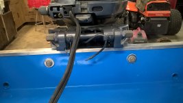
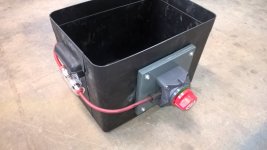
In other news, here's what I came up with for fuse and battery switch mounting.
WP_20220427_13_12_56_Pro.jpg
Feed to the front console fusebox runs through this main fuse and battery disconnect. The switch kills power to everything but the engine, and a direct-wired float switch for bilge pump. The switch was mounted with a few leftover deck board rivets, with the large head inside the battery box, aluminum washers between plastic box and painted plywood mount to avoid trapping moisture.
 
Top