Speed Plateaus at 5200rpm

Texasmark

Supreme Mariner
Joined
Dec 20, 2005
Messages
14,669
I guess I need to re-read my fluid dynamics Physics books. I recall just the opposite. Agree on the other subject you mentioned being suspect. At least he is dealing with a new engine so one could eliminate that. Having had another engine installed and assuming that he maintained his transom height dimensions, with the essentially flat hull at the transom, that should not be a problem.

I find this totally confusing...from his first entry......."The 21P was chosen because they did a sea trial with a 19 and said they could not get max RPM. Now you can get max RPM I just feel speed should be higher."

A 19P is lugging but a 21P gets max RPM??????????? Something is definitely amiss here!
 

Scott Danforth

Grumpy Vintage Moderator still playing with boats
Staff member
Joined
Jul 23, 2011
Messages
49,574
For fluid flow within a pipe, you want laminar flow.
 

jlh3rd

Chief Petty Officer
Joined
Jul 10, 2017
Messages
560
the dimpled golf ball doesn't fly faster, it flies farther because the boundary air doesn't separate as quick which reduces overall drag. The force applied to a dimpled or smooth golf ball (weight and size being equal) would be equal if comparing apples to apples so the initial "speed" would be equal....(F=MxA). There are different types of drag that are a component of Total drag...Different designs, different shapes and drag co-efficients are evaluated and employed to get the desired end result..
Reducing total drag is usually a goal in moving objects, the shape of the object determines which type of drag reduction is used....

There are no dimpled aircraft wings..or boat bottoms....or bullets...

Wings are not spheres....neither are boat bottoms...

those aren't dimples on the boat bottom they're mini protrusions ....they could be contributing to a ventilating issue.....


( I previously had a 1977 Mercury 115 and a safe/comfortable cruising speed of 29mph, and a top speed of 31mph (but with porpoising/reduced control). With the new engine the top/comfortable speed increased to 34mph. The speed plateaus at about 5200rpm (max 6200). Since the engine is under 10 hours I've only had the rpm up to about 5800rpm.)

There is something amiss here, he gets max speed at 5200 rpm......but increasing rpm brings no further increase in speed?
 
Last edited:

Texasmark

Supreme Mariner
Joined
Dec 20, 2005
Messages
14,669
the dimpled golf ball doesn't fly faster, it flies farther because the boundary air doesn't separate as quick which reduces overall drag. The force applied to a dimpled or smooth golf ball (weight and size being equal) would be equal if comparing apples to apples so the initial "speed" would be equal....(F=MxA). There are different types of drag that are a component of Total drag...Different designs, different shapes and drag co-efficients are evaluated and employed to get the desired end result..
Reducing total drag is usually a goal in moving objects, the shape of the object determines which type of drag reduction is used....

There are no dimpled aircraft wings..or boat bottoms....or bullets...

Wings are not spheres....neither are boat bottoms...

those aren't dimples on the boat bottom they're mini protrusions ....they could be contributing to a ventilating issue.....


( I previously had a 1977 Mercury 115 and a safe/comfortable cruising speed of 29mph, and a top speed of 31mph (but with porpoising/reduced control). With the new engine the top/comfortable speed increased to 34mph. The speed plateaus at about 5200rpm (max 6200). Since the engine is under 10 hours I've only had the rpm up to about 5800rpm.)

There is something amiss here, he gets max speed at 5200 rpm......but increasing rpm brings no further increase in speed?
Thanks for adding to this convesation!
 

fatlenny

Petty Officer 3rd Class
Joined
Oct 8, 2021
Messages
85
We are getting into the rough vs smooth hull speed debate here. Golf balls are not a good reference as the goal of golfing is not to skip the ball on the surface of the water. Golf balls are not designed to do this, hence this being any kind of reference in this conversation should be obsolete. The Idea of a roughened surface on the hull is to create tiny air bubbles at the surface, this reduces the drag that water has, reducing the grip the water has on the hull. This can be done right and can be done wrong.

From the photo you shared, this dont look good to me, kinda looks like blisters under the paint or was painted with a heavy nap roller. (High density foam roller should be used.) hard to tell from the photo though. It dont look like a well done paint job. If it was me, I would strip and refinish. But then again I dont think I would be worried about a few MPH.
 

jakec

Petty Officer 2nd Class
Joined
May 23, 2022
Messages
120
Texas Mark, you are reading from and older post, but I later corrected what I had heard from the dealer. It was that they reached max RPM at only 3/4 throttle. So the opposite of lugging, there was not enough resistance at the prop. That is why they went to the 21.

jlh3rd, yes, that is what I'm experiencing.

Fatlenny, I believe the paint was put on with a heavy nap roller in that area. The rest of the boat is sprayed. The guy who did the paint said it was due to client (previous owner) not willing to pay for putting the boat in a lift. So I believe it was painted on the trailer. Sanding this is something that I would not be opposed to doing. However I'm not going to do it if it doesn't matter for the boat performance.

Based on the comments above it seems we are still on the prop as the issue.
 

QBhoy

Fleet Admiral
Joined
Mar 10, 2016
Messages
8,342
Shark skin has more relevance, I’d say. Surely we all remember the rough texture dimpled swim suits that were quickly banned, upon realising their advantage.
 

jlh3rd

Chief Petty Officer
Joined
Jul 10, 2017
Messages
560
your...right..I resign from fluid dynamics.....
anyway
so the question is..why is the prop losing its thrust after 5200 rpm.
Isn't that called ventilation?.... ventilation is air getting into the prop....
I had a ventilation issue with my new motor when turning and trying to up trim...and I could hardly uptrim at all before breaking loose....the dealer hung the new motor for me also...
Lowering the motor about 1 1/2 " ( the last position ) luckily solved the problem for me.....so I was surprised such a small distance made a huge impact....
I can't help but think the motor needs to be lower.......
 

Texasmark

Supreme Mariner
Joined
Dec 20, 2005
Messages
14,669
your...right..I resign from fluid dynamics.....
anyway
so the question is..why is the prop losing its thrust after 5200 rpm.
Isn't that called ventilation?.... ventilation is air getting into the prop....
I had a ventilation issue with my new motor when turning and trying to up trim...and I could hardly uptrim at all before breaking loose....the dealer hung the new motor for me also...
Lowering the motor about 1 1/2 " ( the last position ) luckily solved the problem for me.....so I was surprised such a small distance made a huge impact....
I can't help but think the motor needs to be lower.......
Well now that we have that solved (apologize for any oversight), let's get back to ventilation basics: From Q bhoy wayyyy back at the top:

"Hi. Any pictures of the engine and it mounted on the boat? It may be poorly set up for height perhaps. Could also be to do with the propeller too. Some props just reach their limit of grip and won’t take too much trim at all. You may be over propped too perhaps. Why was the decision to put a 21” on it made ? Was this some after testing for suitability or was it just thrown on at a guess ?"

So with that in mind, let's have some pictures:

With the hull bottom of the boat part in particular, level and the engine exactly vertical, get out your camera and snap:

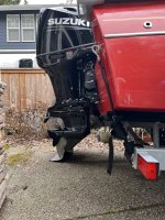
1. From 8-10 feet away, 3' off the ground, a side shot centered at the side of the transom, picking up the entire lower unit and the side of the transom.
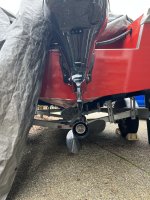
2. Using the same dimensions, get behind the engine still mounted as in #1 and snap a shot.
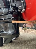
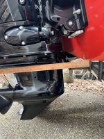
3. Get out a straight edge (yardstick will work) and hold it against the hull extending the end over the front of the AV plate and have someone take a ruler and show the distance between the two with a close up shot from the side.
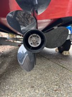
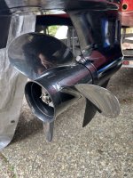
4. A good shot of the prop, interested mainly in blade geometry and material...both rear and side shots up close.

1-3 are to look at the position of the AV plate with respect to the bottom of the boat. The prop pics are to identify anything that might support premature ventilation.
 

QBhoy

Fleet Admiral
Joined
Mar 10, 2016
Messages
8,342
Well now that we have that solved (apologize for any oversight), let's get back to ventilation basics: From Q bhoy wayyyy back at the top:

"Hi. Any pictures of the engine and it mounted on the boat? It may be poorly set up for height perhaps. Could also be to do with the propeller too. Some props just reach their limit of grip and won’t take too much trim at all. You may be over propped too perhaps. Why was the decision to put a 21” on it made ? Was this some after testing for suitability or was it just thrown on at a guess ?"

So with that in mind, let's have some pictures:

With the hull bottom of the boat part in particular, level and the engine exactly vertical, get out your camera and snap:

1. From 8-10 feet away, 3' off the ground, a side shot centered at the side of the transom, picking up the entire lower unit and the side of the transom.
2. Using the same dimensions, get behind the engine still mounted as in #1 and snap a shot.
3. Get out a straight edge (yardstick will work) and hold it against the hull extending the end over the front of the AV plate and have someone take a ruler and show the distance between the two with a close up shot from the side.
4. A good shot of the prop, interested mainly in blade geometry and material...both rear and side shots up close.

1-3 are to look at the position of the AV plate with respect to the bottom of the boat. The prop pics are to identify anything that might support premature ventilation.
Good call 😂. Sounds like it’s something around this is likely.
 

jimmbo

Supreme Mariner
Joined
May 24, 2004
Messages
13,446
Time to get out the Paint Remover. There might be some nice smooth Gelcoat under there.
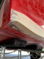
Your boat, was that the one that had the rounded corner where the Transom and the bottom of the hull met?
 

Scott Danforth

Grumpy Vintage Moderator still playing with boats
Staff member
Joined
Jul 23, 2011
Messages
49,574
when the transom was off in this mannor

img_6586-jpg.375853


was the foam tested for water saturation?
 

jakec

Petty Officer 2nd Class
Joined
May 23, 2022
Messages
120
Mark, the boat is not near me so it will be a while until I can take any measurements.

Jimbo, yes it is, but that has been fixed. I attached a progress pic.

Scott, there is no foam.
 

Attachments

  • IMG_7331.jpg
    IMG_7331.jpg
    355.7 KB · Views: 15

Texasmark

Supreme Mariner
Joined
Dec 20, 2005
Messages
14,669
Mark, the boat is not near me so it will be a while until I can take any measurements.

Jimbo, yes it is, but that has been fixed. I attached a progress pic.

Scott, there is no foam.
We'll wait!
 

Stinnett21

Chief Petty Officer
Joined
Jun 24, 2012
Messages
499
Mark, the boat is not near me so it will be a while until I can take any measurements.

Jimbo, yes it is, but that has been fixed. I attached a progress pic.

Scott, there is no foam.
No foam? Serious?
 

jakec

Petty Officer 2nd Class
Joined
May 23, 2022
Messages
120
Haha I don't know how many times I can state it in this thread... no foam. There's a robust debate among boat restorers on foam vs. no foam. I went with no foam.
 

Texasmark

Supreme Mariner
Joined
Dec 20, 2005
Messages
14,669
Haha I don't know how many times I can state it in this thread... no foam. There's a robust debate among boat restorers on foam vs. no foam. I went with no foam.
Following the conversations......
 

jakec

Petty Officer 2nd Class
Joined
May 23, 2022
Messages
120
Here are the requested pics. I’m uploading from my phone so hope they turn out ok. Took one extra photo to show how the plate lines up with the transom pretty spot on.
 

Attachments

  • 02B6EE0A-F9C8-4070-9DA5-934E02E4A622.jpeg
    02B6EE0A-F9C8-4070-9DA5-934E02E4A622.jpeg
    2.9 MB · Views: 25
  • C60FBEF8-2D08-41AD-832B-F35D1D9F23BA.jpeg
    C60FBEF8-2D08-41AD-832B-F35D1D9F23BA.jpeg
    2.9 MB · Views: 25
  • F7163372-DFD4-4A79-B245-7C32D912803B.jpeg
    F7163372-DFD4-4A79-B245-7C32D912803B.jpeg
    2.1 MB · Views: 21
  • 1158C43D-2C9C-4B53-858D-5CC85075478B.jpeg
    1158C43D-2C9C-4B53-858D-5CC85075478B.jpeg
    2.3 MB · Views: 21
  • A5BC2852-C4CC-42F2-9B7E-50CDADFA95E1.jpeg
    A5BC2852-C4CC-42F2-9B7E-50CDADFA95E1.jpeg
    1.7 MB · Views: 24
  • D61890AD-4639-46B2-9F68-2D164C946BAE.jpeg
    D61890AD-4639-46B2-9F68-2D164C946BAE.jpeg
    1.8 MB · Views: 26
Top