Restore/Update 1963 Glastron V143 JetFlite

Kern Fischer

Seaman
Joined
Jun 24, 2013
Messages
51
Woodonglass - thank you for your continuing thoughts and comments.

I agree that despite my best efforts there will still be some flex of the bottom due to wave/wake activity, and as you point out, time will tell if it is a serious issue.

Our college physics professor used to use the example that if a fly landed on the Golden Gate Bridge, it would deflect, albeit very slightly. I believe he was exaggerating slightly to make a point that everything will deflect due to outside forces and the strength of the object and the amount of the force will define the amount of deflection. And enough force will fail the object.
 

Kern Fischer

Seaman
Joined
Jun 24, 2013
Messages
51
After the hull was mounted on the rotisserie, it was rotated so it was at about a 45 degree angle. Then the lower side of the stringer to hull joint was closed with masking tape. Then epoxy resin was flowed into the joint by gravity and a generous radius was formed between the side of the stringer and the hull bottom. The epoxy used for this radius had a filler of sawdust to give it some viscosity to hold the desired shape.

IMG_0010.JPG The hull positioned to fill the stringer/bottom joints and add the radius.

Then the hull was rotated to 45 degrees in the opposite direction and any additional voids were filled and a radius was formed on the other side of the stringer. The radii were formed on the stringer bottom joints to insure that the fiberglass cloth that would be added later would form easily into the corner and could be wetted for a good bond to the stringer, radius, and bottom with no voids where the cloth would not conform to the surfaces.

With the hull still at the 45 degree angle, one side of each stringer/hull joint was wetted and a two inch layer of fiberglass cloth was placed on the joint and completely wetted. Then a four inch layer was placed over the first layer, insuring that the top edge was flush with the top of the stringer so the stringers are fully covered by cloth and resin.

IMG_0012A.JPG The layers of cloth positioned as they will be bonded into place to strengthen the joint and enclose the stringer sides.

The stringers are now fully enclosed in resin except for the top surface. This will be coated and sealed when the floor is laid in position and bonded in place.
 

Woodonglass

Supreme Mariner
Joined
Dec 29, 2009
Messages
25,929
I must say...If you're gunna work with epoxy, having a rotisserie IS the only way to go. WOW!!! How easy can it get!!!!:D;)
 

Kern Fischer

Seaman
Joined
Jun 24, 2013
Messages
51
I think that even if I were working with polyester, I would still have built the rotisserie as it allows using gravity to flow the resin into spaces where it might run out otherwise.

That said, mine was relatively simple to build. A heavier, larger hull would require a stronger, more complex structure and obtaining the balance point for easy rotation might be more difficult. If I had removed the deck, properly supporting the hull on the rotisserie would have probably required a complex external and/or internal support structure that would have held the hull in the proper shape without distortion.
 

Woodonglass

Supreme Mariner
Joined
Dec 29, 2009
Messages
25,929
Nah Polyester only has a 25 minute working window. Once you get used to using it, you learn how to manipulate it. Epoxy on vertical surfaces is a BEAST. I just keeps flowing DOWN and you have to keep dragging it back up onto the glass until it starts to "Kick" and will stay where your want it. Too much of a hassle for me. I've used the fast set epoxy and that's a bit easier but still slower than Poly!!!
 

Kern Fischer

Seaman
Joined
Jun 24, 2013
Messages
51
While hull work was active, the seat shells and console were also being restored. These items were fiberglass moldings with a leather like texture pattern on the outside surfaces. Starboard had painted both the seats and console but had not addressed the seat shell stress cracks that had occurred during usage.

To repair the damage to the seat shells would require significant grinding of the surfaces so new glass matt and resin could be added without significantly increasing the thickness. The repair work would result in new surfaces that would not have the texture of the originals. It was decided to make all the outside surfaces smooth. This will not be original but the new surfaces will be much easier to keep clean and will match the surface finish of the other white painted areas on the hull and covers.

DSCN8235.JPG
Seat shell repairs involved significant rebuilding of the shell structure, filling cracks and recontouring.

DSCN8195.JPG
Repairs to the seat bottom.

DSCN8611.JPG
The shell back after repair, filling, and sanding.

The seat shells, as received from City Auto Body, were beautifully finished on the outside. The insides were still rough and needed sanding before a final finish was added. The bottom board was also smaller than the seat base so the loads were not distributed as widely as possible. The shells were sanded on the inside and the bottom boards replaced with new, larger items. The sides of the boards will be resin blended into the sides of the shell so there will be no recess around the perimeter of the board. This will also transfer any movement loads into the sides of the shell rather than concentrating them primarily in the bottom.

IMG_0003.JPG
The seat shells and console as received after repair and paint.

IMG_0014.JPG
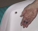
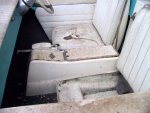
The original bottom board after repair of the mounting hole areas. Note the rough interior surfaces of the shell and the channels around the bottom board, making the seat shells hard to clean.

IMG_0016.JPG
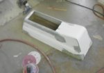
The interior of the seat shell after removal of the original bottom board and sanding of the interior surfaces.

IMG_0083.JPG
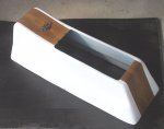
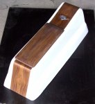
The new bottom board bonded into place. It covers the entire bottom surface to spread the loads over more area and provides a smooth bottom surface.

When riding on rough water, the forces against the seat shells are fore and aft on the backrest and vertically on the cushions. The fore/aft motions have to be resisted by the mounts on the base. This places stresses where the base and backrest join. The inside surface of the sides in these area was reinforced with a layer of thin fiberglass cloth and resin and faired into the sides.

When fitting the seat back into the shell it was noted that there is a large cavity between the seat back board and the inner shell. In case of a sinking, this volume would fill with water and contribute nothing to flotation. It was decided to add foam into this volume to assist in flotation. A calculation showed that foam could be simply added that would contribute about 10 pounds of flotation per seat. The completed foam shapes were epoxied for a smooth surface and then painted with the interior paint. The foam was attached to the rear of the backrest cushion with a few silicone dots. This will allow easy removal if desired in the future.

IMG_0063.JPG
The backrest foam flotation. The left assembly has been bonded together but has not been shaped. The right assembly is shaped and is ready for epoxy coating.

IMG_0065.JPG
Trial fitting the flotation foam to the trimmed seat backrest. The backrest/foam assembly was also trial fitted into the seat shell to be certain that all parts would fit properly.

The backrest pad is attached to the seat shell from the rear by five screws. These screws are exposed so chrome plated trim screws with an integral cupped washer were chosen. The edges of the washer will cut into the paint so o-rings were selected to fit under the washers as a cushion.
IMG_0086.JPG
The backrest attachment screws showing how the O-rings were inserted under the trim washers to minimize paint damage from the washers.

Originally the seats were mounted with two screws, front and rear, on the centerline. This allowed the passenger seat to be reversed for observing a skier. The anchors were blind toggle type mounted to the floor. After some time the hardware corroded and the anchors tore loose when trying to remove the bolts. With only two bolts, the stresses at the holes through the seat bases caused some damage and cracking around the mounting holes.

The new design includes four mounting bolts using brass hardware because it was easily brazed to create the unique anchors and bolts. The anchors are flat plates with four holes to screw them to the floor. The bottom has a nut brazed to it. The bolts are standard slot head machine screws with a rod brazed across the head to create a type of ?wing bolt? for easy tightening by hand.

IMG_0093.JPG
The new mounting hardware for the seats. Also note that the interiors of the seat shells have been painted to provide a good appearance and a surface that is easily cleaned.

Where the mounting bolts penetrate the seat bases, the holes are lined with short pieces of brass tubing, epoxied in place. This prevents wear on the wood bores and keeps any moisture from penetrating the wood. The tubes are shorter than the thickness of the seat base so the mounting screws will always bear on the wood base boards rather than the tubes. The washers under the mounting screws are bonded in place with silicone so they will not be a loose item to get lost.

IMG_0088.JPG
The completed seat assemblies ready for installation. The left unit shows all of the components prior to assembly. The right unit shows the final appearance of the seats. The bottom cushion of each seat is removable to access the shallow storage compartment under the cushion. As noted earlier, the backrest cushions are screwed to the seat shell and remain in place during use.
 

Attachments

  • IMG_0086.JPG
    IMG_0086.JPG
    48.8 KB · Views: 1

Kern Fischer

Seaman
Joined
Jun 24, 2013
Messages
51
As shown on the pre-restoration picture, the console originally had a gold mylar waffle pattern trim on the front and rear sections. This trim could not be saved, was probably not available, and looked rather cheap. The original lid and hinge were crudely made and the hinge was visible and not very attractive. The hinge was at the front of the lid, which was not the most convenient to use. Some changes and redesign were in order.

CONSOLE LT.JPG
The console before restoration showing the crude design and construction.

The console required minor repair work and then the outer surfaces were filled and sanded smooth to match the seat surfaces.

DSCN8227.JPG
Minor repair work prior to filling, sanding, and painting to match the seat shells.

**** at Starboard suggested making the new lid out of wood. This led to the decision to trim the front and rear of the console in wood veneer and a further decision to trim the instrument panel in wood veneer. A visit to a hardwood store resulted in choosing teak for the wood trim, based on the graining patterns. This is appropriate as teak is a typical wood used on boats.

The new design will have the wood lid and trim, edged in chrome strips to match the strips being used on the foredeck and side deck trim. For more convenient access, the lid will be hinged on the port side, using a white plastic hinge strip.

The inside of the console was sanded to remove some of the roughness prior to paint. A wood strip was made to fit into the upper port corner to provide a mounting surface for the hinge. This strip was bonded in place with epoxy resin and faired with epoxy mixed with the microballoons. The inside of the console was then painted.

IMG_0155.JPG
The inside of the console after sanding smooth and painting.

IMG_0010.JPG
The hinge mounting strip bonded into place in the port top corner of the console.

IMG_0016.JPG
The installed hinge.

Wood veneer was cut to fit the front and rear center areas of the console and bonded with contact cement. The bend at the top rear was tight enough to crack the veneer so it was soaked in water prior to applying it to the surface. After the cement had set, the top and bottom edges of each area were trimmed to match the console surfaces. The veneer was coated with many coats of clear polyurethane with sanding between some of the coats. The final coat was sanded smooth and rubbed with steel wool. The resulting surface looks very natural and is smooth and satiny to the touch. It will also be easier to repair, if necessary, as compared to a highly polished surface.

IMG_0014.JPG
The wood veneer bonded in place and finished with polyurethane.

IMG_0018.JPG
The completed wood parts, finished and in place.

The original idea for the trim strips on the lid was to have them running around the sides on the slanted surfaces and mating to the front and rear veneer trim. This would have been harder to fit and the trim line would be bulged out around the lid. Instead, it was decided to run the strips straight along the edges at the top of the lid, in line with the veneer trim. To get the desired alignment, the lid had to be made thinner. The router bit was used to cut 3/16 inch off the top of the lid. This moved the upper outer edges outboard enough to align with the veneer trim.

Brass trim strips were fitted to the front and rear surfaces of the console, the edges of the lid, and the front and rear edges of the console opening. These were sent out for polishing and chroming prior to final installation.

IMG_0020.JPG
Trial fitting the brass trim strips prior to polishing and plating.

After the trim strips were returned from polishing and chroming, they were installed on the console using clear silicone seal to bond them to the surface. Silicone has been used on other similar applications with good success and was much simpler than trying to create some mechanical means of attachment.

IMG_0075.JPG
The finished console ready for install in the hull.

IMG_0078.JPG
With the lid partially open, the trim strip across the rear of the opening is visible. There is a matching strip at the front of the opening.
 

Attachments

  • DSCN8227.JPG
    DSCN8227.JPG
    15.5 KB · Views: 0
  • IMG_0014.JPG
    IMG_0014.JPG
    91.6 KB · Views: 1
  • IMG_0018.JPG
    IMG_0018.JPG
    109.2 KB · Views: 1

Kern Fischer

Seaman
Joined
Jun 24, 2013
Messages
51
The original transom board was full height in the center and tapered down at each side to a height of about six inches. The outer skin of the hull angled rearward at the outboard ends so the outer portions of the transom board did not bear directly on the skin. During early usage, cracks developed at the corners where the transom met the sides of the motor well due to flexing of the upper portion of the transom.

To reinforce the transom and spread the loads over a greater area, a 6 X 6 X 3/8 inch aluminum angle was installed with one leg between the transom board and the rear surface of the motor well and the other leg under the bottom of the motor well. This stabilized the transom by spreading some of the torque loads into the bottom of the motor well. No further cracking occurred.

The original transom board was still in the boat when the decision was made to start the restoration. It was water soaked and had swollen in thickness to a size that would not allow the motor clamp to slide down over the top of the transom.

TRANSOM ROT.JPG
An exploratory hole cut into the top of the transom. Note that the outer skin has separated from the transom board and the board has swelled in thickness at the center.

Starboard Marine replaced the center section of the transom board but left the outer ends in place. During the replacement of the center section, they also cut away the outer skin on the transom center and later replaced it with a new skin. They claimed to have adequately bonded the new center section to the old outer sections. I was not fully convinced that the three piece board was going to be strong enough and asked that they add a full width board to strengthen the area. They bonded and screwed a new board to the front of the new center and existing sides. It did not extend upward beyond the bottom of the motor well.

IMG_7315R.jpg
The replacement center section as installed by Starboard Marine.

IMG_7430R.jpg
The requested wider reinforcing board installed in front of the new center section.

While cleaning up the inside at the stern and grinding away some of the fiberglass that was not adequately bonded, the tops of the outer sections of the original transom board were exposed and found to be wet and delaminated. The area was ground away on each side to expose more of the board for further evaluation of needed repairs.

IMG_0031.JPG Initial cutting of the sides to expose the original side sections of the transom board. Both sides were wet and the layers were separating.

IMG_0045.JPG Further removal of the old side boards. Starboard claims to have had a good bond between the new and old sections. I do not feel that was accomplished.

The new reinforcing board was cut out to expose the inner surface of the new transom board that Starboard had installed. This surface had been coated with fiberglass cloth and resin. Further cleanup and smoothing of the inner surfaces of the rear corners was completed as preparation for the additional build up of the transom to spread the motor torque loads.

IMG_0053.JPG The reinforcement board after removal. It alsready shows discoloration from being wet, probably during the delivery rain storm. It obviously was not fully encapsulated in resin to keep it from getting water soaked.

All the old, wet, and rotted sections of the original transom structure were cut out. The bottom cross board below the new center section was also weak with some rot so it was cut out and a replacement board was fitted.

IMG_0076.JPG
 

Kern Fischer

Seaman
Joined
Jun 24, 2013
Messages
51
The site would not let me post the complete story of the transom rebuild so this is part 2.

There was no room to caption the previous picture and it was posted without caption. The picture shows the removal of the bottom transom board with the boat upside down on the rotisserie. The new stringers can be seen at the top. Also visible is the bottom leg of the aluminum angle near the bottom of the photo. It is bonded to the underside of the motor well and has holes drilled in it for lightness.

An analysis was made to determine the best way to rebuild the transom structure to insure that it will be strong and long lasting. The transom of this boat is 17 inches high. The forces of propulsion create a torque effect on the transom where the motor mount attaches. This torque is pushing forward at the bottom of the motor mount (10 inches from the top) and pulling aft at the upper screw clamps (2 ? inches from the top). So most of the forces on the transom are acting on the upper half. The previously installed aluminum angle transfers some of these torque forces into the bottom of the motor well, increasing the area to resist the forces.

The original transom board design does not optimize the spread of maximum forces into the upper sides of the transom for additional load carrying area. The new design will have the widest portion of the transom board at the top with the width tapering down toward the bottom below the outer sides of the motor well. The original center section as installed by Starboard Marine will be left in place.

IMG_0008C.JPG The inside of the starboard transom after grinding away all the old excess material. The new center board is the light area to the right. One of the old stringers is also visible at the lower right with its poor capping and broken sections.

Prior to installing the new transom side boards, a layer of heavy fiberglass cloth was bonded into place reinforcing the upper transom to rear deck area from the motor well outboard about 10 inches. This will transfer any upper transom forces into the rear upper deck, further spreading the loads.

IMG_0063A.JPG
The load spreading cloth bonded in place between the upper transom and stern side deck.

Because the transom board will now be three pieces, a very stiff joint will be required between the center and outer boards to minimize flex and maximize force transfer. This will be accomplished by adding two structural elements into the design. The first will be two layers of interwoven fiberglass cloth that will be fitted into the joint between the center and side boards. The cloth will be inserted as two ?S? section pieces running for as much length of the joint as possible. The ?S? sections will be formed by having the transom skin end of one piece behind the center board, routed through the joint between the boards, and attach to the front of the side board. The other piece of fiberglass will have its transom skin end behind the side board, pass through the joint, and bond to the front of the center board. The two pieces of fiberglass cloth were interwoven to be able to create this joint. Having the hull on the rotisserie allowed turning it on its side to be able to flow resin down into the gap between the transom skin and center board to adequately bond the glass cloth into place with no voids.

IMG_0053A.JPG
The cloth pieces cut and interwoven to be placed into the joint between the center and side transom boards.

The other load spreading part of the design consists of ? inch stainless steel rods that are inserted into horizontal holes drilled between the aluminum angle and the center transom board. These rods will extend outboard onto the new side board sections and will be bonded to both center and side boards. Rearward loads on the upper transom will be transferred into the aluminum angle, then to the stainless rods, outward to the side boards, into the outer transom and rear deck areas.

IMG_0070.JPG
The side transom board bonded in place. Note the cloth bonded in place on each side of the board joint. Similar cloth faces are bonded to the back side of each board between the board and the transom skin. The center board has grooves cut into the surface to accept the stainless steel load transfer rods.

IMG_0002A.JPG
The stainless rods bonded in place. The side board has been fully bonded on the upper and inner edges. The white color of the resin is due to the addition of microballoon filler.

IMG_0011A.JPG
The completed transom structure ready for paint. All wood and the stainless rods are totally encapsulated in resin so there should be no chance of the wood ever getting wet.

The rearward forces on the upper transom will now be distributed to the bottom of the motor well, to the upper outer transom and to the upper deck alongside the motor well side wall. With this redesign, the transom should resist water penetration, be quite strong, and easily capable of handling motor horsepower ratings of over 100 horsepower. However, the original 65 horsepower motor will be kept with the boat as long as I own it.
 

Kern Fischer

Seaman
Joined
Jun 24, 2013
Messages
51
This information about the foredeck improvements is rather long, so will be posted in two parts.

The foredeck was made of relatively thin fiberglass and tended to flex when crawling on it to board, paddle, or retrieve the anchor. This flexing produced spider cracking in the gel coat.

The factory support for the foredeck consisted of five wood cross braces that were tabbed to the underside of the foredeck. These were shaped approximately like the underside of the deck but were not fitted precisely. To fill any gaps, the factory used corrugated cardboard as shim strips. Starboard Marine attempted to improve this situation by making wood shims to give better support. There was still no support for the deck between the cross braces.

The following pictures were taken with the boat upside down on the rotisserie so the working area was more accessible and horizontal to provide good flow for the resin.

IMG_0032.JPG The original deck supports. Note the cardboard factory shims and the later wood shims added by starboard.

As originally delivered, the boat had flotation foam planks tied to the foredeck cross braces. I loaned the boat to my brother for a couple of seasons and when it was returned, these planks were missing. I assume they gave him some trouble at some time so he just removed and discarded them. Their volume was inadequate to keep the boat afloat if swamped.

The new goal for the foredeck is to create a support system that will provide a solid, non-flexing deck surface, along with adding flotation to the front of the boat. The calculated flotation that will be added is about 200 pounds in the foredeck structure.

A design was created using one inch wide strips of ? inch plywood to provide deck support. These will be laid on a 7 by 9 inch grid so the rectangles between the strips will be 6 by 8 inches. The one inch strips provide more support area than the ? inch original cross braces, even including their tabbing. The grid also adds support area by providing six cross supports and seven longitudinal supports.

IMG_0005.JPG Removing the factory cross braces and grinding the surface smooth to provide a good bonding are for the grid.

IMG_0018.JPG The underside of the deck showing the grid layout for the plywood strips.

The center of the deck has a section that is 15 inches wide and is raised about ? inch above the main deck. The underside of this raised area will be fitted with three longitudinal wood strips with foam between them. The foam is not available in ? thickness so strips ? thick were cut from the one inch sheets. These were then laid side by side to fill between the longitudinal wood strips.

IMG_0005_1.JPG The foam that will be used under the deck with the grid blocks and the 1/4 inch thick cut strips.

The grid will be bonded to the underside of the deck for good conformity and support and built up to four layers of plywood for a one inch height. At the grid intersections, the through strip will alternate with one layer having the cross strips going through the intersection and the longitudinal strips being interrupted. The next layer will have the longitudinal strips running through and the cross strips interrupted. All strips were bonded in place, one layer at a time.

The planned grid for the deck support is made up of many pieces cut, laid, and bonded in place one at a time. The total listing of the pieces follows:

Plywood strips
17 Longitudinal - varying lengths
62 Longitudinal - 8 inch
12 Cross - varying lengths
64 Cross - 6 inch
28 Short - varying lengths

Foam
12 Strips - 1/4 X 1 - varying lengths
24 Blocks - one inch thick - 6 X 8 inches
20 Blocks - one inch thick - varying sizes and shapes

IMG_0024.JPG
Starting to fill the raised center area of the deck. The plywood under the weights is temporary to spread the loads over all the strips. The first cross strip is also in place under the front weight. The light colored plywood ovals are deck reinforcements for the cleats. The corners are rounded as this keeps from concentrating stresses as would happen with square corners.

IMG_0004.JPG
The completed center area with a partial first layer of strips. The first layer has thecross strips full width and the longitudinal strips are short, between cross strips.

IMG_0068.JPG
The grid about half completed. The cross strips lying at angles are waiting to be bonded into position between the already placed longitudinals.
 

sphelps

Supreme Mariner
Joined
Nov 16, 2011
Messages
11,471
Pretty cool technique on the cap .. Should make it very strong and light weight ..
 

Kern Fischer

Seaman
Joined
Jun 24, 2013
Messages
51
Foredeck structure and flotation continued.

After the grid was completed, the first layer of foam blocks was inserted into the grid voids and bonded into place. Access holes were left in the foam for deck hardware installation and notches were cut around the edges for rub rail hardware installation. A length of clear tubing was bonded to the center strip to use as a conduit for routing the wires to the bow light.

IMG_0101.JPG
The completed grid with a few of the foam blocks that will be inserted in the grid voids.

IMG_0135.JPG
The completed first layer of foam within the grid. Note the clear vinyl tube bonded to the center strip.

After the first layer was complete, panels were cut and fitted for the second layer. To ease fitting and bonding into place, this layer was made using nine inch wide panels whose edges were centered on the cross strips. The panels were weighted to get conformity to the curvature of the deck during curing of the resin. As in the first layer, access was provided for deck and rub rail hardware.

IMG_0145.JPG
The beginning of the second foam layer bonded into place.

In previous usage of the boat, the paddle and boat hook were just stowed loosely behind the port side panel. A better stowage system was desired so brackets were made from wood to stow both under the foredeck on the port side. The design was created to make it easy to remove the items from the brackets and to replace the items after usage. These brackets were bonded to the wood cross pieces of the grid and cutouts for them were made in the top foam layer.

IMG_0159.JPG
The paddle and boat hook brackets. The brackets on the right will be forward near the bow and the left bracket will be near the instrument panel. The left bracket is shown inverted relative to the right brackets, for clarity.

IMG_0166.JPG
The finished brackets with carpet padding installed, ready for installation. For purposes of clarity and to get them all into frame, the rear bracket is inverted relative to the front two and the brackets are closer together than they will be in the boat.

The fore end of each item will be supported by its respective bracket. The handle end is lifted into place and held in place by bungee cords that were created for this purpose. They were made by cutting a longer bungee to the desired lengths and bonding the ends into electrical terminals. The terminals slide over stainless tubing that is bonded into the bracket. The cord portion then hooks over stainless steel pins that are bonded into the brackets. To keep the paddle and hook from sliding rearward out of the front supports, stainless steel pins were inserted into the centers of the curved support areas and holes were drilled into the handles of the paddle and hook. When the handles are secured into the rear bracket, the pins engage the holes and prevent any aft movement of either item.

IMG_0169.JPG
The brackets mounted in position onto the wood grid, to the right of center in this picture.

IMG_0175.JPG
The boat hook and paddle stowed in position in the brackets. This picture was taken while the hull was still upside down on the rotisserie and was then interted to show what the installation would look like in use. The handle ends are easily reached under the port side instrument panel. When the interior work is finished, the surfaces will be painted with a light grey paint to provide a consistent look and brighten the under deck area.

The foredeck is now very solid. During the interior work a slight amount of damage occurred to the new paint and the new foredeck surface is not as smooth as it was after paintwork was complete. After all interior work is completed, the decks will be resanded to get them fair again, and repainted.
 

Attachments

  • IMG_0166.JPG
    IMG_0166.JPG
    44.1 KB · Views: 1

scoutabout

Lieutenant Commander
Joined
Oct 14, 2006
Messages
1,568
Very impressive work and a really cool boat! Looking forward to following along.
 

Kern Fischer

Seaman
Joined
Jun 24, 2013
Messages
51
The rebuild of this boat with its many changes is adding weight to the hull so various ways of taking off weight are being considered. The steering assembly was surprisingly heavy so lightening some of the parts was desired. The rear mounting bracket needed refinishing and it was decided to lighten the parts before painting. The original assembly was held together with two rivets. One of them was not seated tightly so there was some slop between the parts.

IMG_0097.JPG
The original transom mounting bracket for the aft end of the steering cable.

One end of the rivets was ground away and the rivets removed to separate the parts. There was a thin plastic washer between parts at each rivet position. These were worn and were deformed from the heat of grinding the rivets.

Metal was removed from each of the parts where it was not critical to strength or function. The parts were then painted. Reassembly was done with stainless steel shoulder bolts, new nylon washers, and self-locking stainless steel nuts, resulting in a snug, corrosion resistant assembly.

IMG_0044.JPG
The finished bracket assembly with smooth, accurate movement.

The original assembly weighed 600 grams and the revised assembly weighs 470 grams, for a 130 gram saving (about 1/3 pound). Not a great savings when considering the time required, but the resultant assembly is also much better from a functional standpoint.
 

Kern Fischer

Seaman
Joined
Jun 24, 2013
Messages
51
NEW INSTRUMENT PANEL - Posted in two parts due to length.

The original instrument panel was plain with the steering wheel mount and a small push-pull two position switch for the anchor and navigation lights. The top of the panel had a cover that was a plywood board trimmed in vinyl that matched the front deck vinyl. When purchased, this vinyl was discolored in a small area. An inquiry to Glastron resulted in them sending a replacement vinyl piece for no charge - very good customer relations.

STRG WHL.JPG
The plain panel face, as delivered.

When the upholstery and deck trims were reupholstered, the instrument panel top cover was upholstered to match. For this restoration it is being recovered again with trim to match the rest of the interior and deck trim.

Early in the life of the boat, surface mount speedometer and tachometer instruments were installed along with a cigarette lighter/map light combination. The speedometer was functional but the tachometer was never connected. These instruments were later removed.

While creating the new structure under the foredeck, the instrument panel back-up board was bonded into place behind (toward the bow) the original fiberglass instrument panel. Clearance holes were cut into the fiberglass for the new gauges and switch panel.
IMG_0037.JPG
The original panel back board at the bottom - it did not extend full height. The center board is the new back board, extending full height behind the fiberglass. The top board is the new face board that will be laid over the original fiberglass.

IMG_0042.JPG
The new back board with holes cut for the gauges, steering, and switches. Trial fitting the hardware into the new face board.

The new instrument panel face will have a wrap-around design that will extend aft along the sides to meet the side deck trim. It will get a teak veneer facing to match the console trim. Instrumentation will be upgraded to a VDO speedometer, tachometer, fuel gauge, and hourmeter. The instruments had black bezels when originally purchased. Chrome bezels are more appropriate for the era of the boat so the instruments were sent to a VDO repair facility and the bezels were changed to chrome. A new switch panel will have switches for the anchor light, navigation light, interior lights, and rear compartment blower.

To create the wrap around and extensions of the panel, side pieces were cut from ? plywood and the main panel and side panels were grooved on the back for 1/8 inch stainless steel rods. These rods were formed to conform to the corners at the ends of the original fiberglass panel. Then the grooves in the wood parts were filled with epoxy and the parts were positioned over the rods and left while the epoxy cured. The epoxy used for this purpose was JB Weld as it has great bonding capabilities to metal.

IMG_0014.JPG The new face board on the right and an extension at top, with the grooves cut into the back sides for the rods. The rods are shown taped into position ready for the grooved boards to be epoxyed into place. Waxed paper is used behind the rods to prevent the epoxy from sticking to existing surfaces.

IMG_0018.JPG The new face board and side extensions clamped and taped into place while the epoxy cures.

IMG_0044.JPG The face board with the side extensions attached by the stainless steel rods.

After the rods were bonded into place as a basis for the corner structure, strips of ? plywood were cut and grooved on the back sides so they could be bonded to the stainless rods to form the corners. The gaps between the strips were then filled with a resin/microballoon mixture to create the front and rear corner surfaces and the surfaces were sanded to the desired contour. A layer of glass cloth was applied to the front surface for strength. Then the outer edges were sanded to the final shape desired for the panel face.

IMG_0056.JPG
The plywood filler strips bonded into place to form the corner curvature.

IMG_0059.JPG
The back side of the corner structure with the gaps filled with an epoxy/microbaloon mix. Note how the rods form the basis for the corner shape.

IMG_0058.JPG
A layer of fiberglass cloth was added to the front of the corner to provide extra strength and a smooth surface for bonding the veneer.
 

Kern Fischer

Seaman
Joined
Jun 24, 2013
Messages
51
Instrument Panel - Part 2
IMG_0051.JPG
The fully formed panel being trial fitted into the hull.

It was desired to attach the new panel to the existing panel surface with hidden fasteners. Prior to adding the face veneer to the panel, flat head screws were installed in the panel with washers and nuts on the back side. This hardware was bonded into the panel with epoxy resin. Holes were drilled in the original fiberglass panel to accept these screws. Then fender washers and nuts were added on the back side to hold the entire new panel in place.
IMG_0065.JPG Closeup of the mounting screws countersunk into the face panel and bonded into place with epoxy. The heads will be covered with veneer and will not be visible.

IMG_0067.JPG Closeup showing how the front panel will be fastened onto the hull instrument panel face. The white board simulates the hull panel and is cutaway to show the hardware relationship to the hull panel and the new face panel.

The teak veneer was then bonded to the new panel structure using contact cement and the various holes were cut into the veneer and the edges were dressed smooth. Then the veneer was coated with several coats of polyurethane with sanding between some of the coats. The final coat was sanded and then rubbed with steel wool for a smooth, satin finish like the console. One forum member commented that steel wool particles left on the surface may show rust over time. To minimize this possibility, a strong magnet was swept over the surface after finishing.

IMG_0070.JPG The new face panel and the veneer after coating with contact cement. The ends were left uncoated for the initial install and were later coated and bonded so the veneer could be tightly fitted into the corners.

IMG_0074.JPG For the initial positioning of the veneer to the panel the parts were separated by waxed paper except for a small area at the top center. The veneer was positioned and the small area was bonded. Then the waxed paper was progressively removed and the veneer was pressed to the panel with a small roller.

IMG_0099.JPG The completed panel after trimming the veneer and applying and finishing the polyurethane.

The instruments and switch panel were installed and the entire assembly was wrapped and put into storage awaiting final installation. The final installation will have chrome strips along the angled end and bottom edges. These strips will match strips used to edge the vinyl deck trim and console trim.

IMG_0108.JPG The panel with gauges and switch panel installed. The open hole on the starboard side is for the steering shaft.

IMG_0110.JPG Closeup detail of the gauges.

IMG_0111.JPG Closeup detail of the new switch panel with the hull color accent.
 

Kern Fischer

Seaman
Joined
Jun 24, 2013
Messages
51
As originally built, the interior side panels were terminated near the instrument panel at the front and near the rear of the open area at the rear. This left some of the hull interior exposed at the front and left the entire rear area open. The boat ran most of the time with the tonneau covers in place so the open rear area was not exposed. However, if it were finished it would look better when the covers were off the hull.

CONSOLE L.JPG
The original side trim panels did not extend forward into the foot well area and much of the hull interior was visible.

STBRD RR.JPG
The side panel rear stopped at the end of the cockpit area. The entire rear compartment was open and did not always look tidy.

The plan is to enclose the rear area to hide the battery and fuel tank as both will be permanently mounted. The side trim panels will be extended forward to provide a more finished look in the footwell area and rearward to meet side extensions of the rear closure panel. The rear panel will have a hinged door for access to the rear compartment for priming the carburetors and inspection of the compartment. The rear panel will also be removable for any servicing of the components in the rear compartment.

Closing the rear area will present the possibility of gasoline fumes accumulating in that space with the possible hazard of an explosion. Additional venting will be provided for air flow when under way and a blower will be added for venting prior to starting the motor.

New side panels were cut from ? inch plywood and fitted to the shape of the desired coverage. Allowance was made at the bottom for the floor carpet and the top edge was cut to closely match the chrome trim that will be installed around the instrument panel and the side deck trim. A cutout was made in the inner side deck extensions and in the new side panels for the new interior lights that will be added.

SFTRIM.JPG The new side panels extend forward to beyond the floor step and will provide a more finished look to the foot well areas.

SRTRIM.JPG The rear of the side panel stops short of where the original was. The new rear panel will wrap around to meet the side panels.

Per a suggestion from Dave at Schober?s Trim, the panels will be attached to the inner deck extensions using the plastic tree type fasteners used for many automotive panel attachments. Holes were drilled in the plywood side panels for the fasteners and matching holes were drilled into the side deck extensions.

The main rear panel was cut from 3/8 plywood and the side extensions were ? plywood. The curved corner areas were made in the same way as the corners of the instrument panel extensions. The main panel and hinged door tended to warp when laid out in any way except perfectly flat, so stiffening ribs were added to both to maintain flat surfaces. Various gaps were created between the panel edges to allow for the thickness of the vinyl trim where it wrapped around panel edges. The rear panel will be held in place by stainless steel brackets and machine screw fasteners.

IMG_0018.JPG Trial fitting the new rear panel prior to making the corner extensions. The access door has been cut and the plastic hinge is the white line at the bottom.

IMG_0012.JPG The side and rear panels fitted into place for final alignment of the edges. Note the stiffening ribs on the back of the access door to keep it flat during use.

The panels will be upholstered primarily in white but will have an aqua stripe, consisting of three pipes, that will extend from the foot well area on one side all around the rear and then forward to the foot well on the other side.

IMG_0030.JPG The trimmed panels sitting in their approximate positions. The edges and stripes are not aligned because the panels are not fastened into their final positions.

IMG_0031.JPG Another view showing the continuity of the stripe from one side to the other. The large round holes near the bottom of the rear panel will be filled with white plastic vents. The top of the rear door will have quarter turn latches as shown on the port upper corner of the door.

The inside of the rear compartment door will be occasionally exposed during operation of the boat so this surface was fully trimmed in a black material like the bottoms of the seat cushions to look good when open.
 

Attachments

  • CONSOLE L.JPG
    CONSOLE L.JPG
    134.2 KB · Views: 2

Kern Fischer

Seaman
Joined
Jun 24, 2013
Messages
51
Continuing work on the bottom structure was interrupted by the move to the new residence and the project was delayed for about a year. To aid in the move, the floor was temporarily installed and the boat was used to carry a wide variety of items to the new location.

Picking up the story line where we left off, the stringers were installed into the hull and bonded into place. A post indicated that it was not usual practice to bond the stringers to the bottom fiberglass as this created hard spots along the stringers and the fiberglass bottom would flex between the stringers and cause gel coat cracking.

This flexing may not be a problem with this build as the volumes between stringers are being filled with rigid foam that will be bonded into place with resin. Then the floor will be bonded to the tops of the stringers and to the foam, creating a rigid assembly that should provide good support for the bottom.

The foam and resin are being used to completely fill the underfloor cavity for two reasons:
1. To provide flotation for the hull. Due to its irregular shape, it is difficult to precisely measure
the foam volume. The estimated flotation due to the underfloor foam is about 200 pounds.
2. To prevent any water entry into the lower hull, thus keeping the wood structural components
dry and strong. Every piece of foam and every wood part will be completely encased in epoxy
resin. No screws will be penetrating any of the wood parts without being fully encased in
resin.

Fitting the foam pieces into place was made more time consuming by the bottom shape being a slightly rounded very shallow vee from the keel to the chine area. At the keel the foam thickness was slightly over two inches, tapering to a pointed edge at the chine. Each part had to be shaped and fitted and no two were alike. Fortunately, the foam is easy to cut, file, and sand to the desired shape. Each cavity between the stringers was filled to a level that was flush with the tops of the stringers.

IMG_0128.JPG The first layer of foam laid into place and bonded to the bottom with resin.

IMG_0131.JPG Looking forward - the top layer of foam. Some blocks are slightly higher than the tops of the stringers and will be trimmed flush. Each block was bonded the the lower blocks using full resin coverage of the surfaces.

IMG_0133.JPGLooking aft - ready for trimming the top blocks.

A minor change was made to the shape at the front of the bilge well. The original front surface for the well was vertical and the corners were difficult to clean. The new front surface was set at a 45 degree angle for easier cleaning.

IMG_0139.JPG
Looking forward - the tops of the blocks have been trimmed. There are still some cracks and cavities that need to be filled so the blocks are totally encased in resin. These gaps will be filled with a resin/microballoon mixture before installing the floor.

IMG_0138.JPG
Looking aft - the board at the front of the bilge well has not been installed yet.
 
Top