Restore/Update 1963 Glastron V143 JetFlite

Kern Fischer

Seaman
Joined
Jun 24, 2013
Messages
51
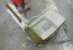
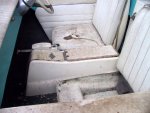
The seat shells and console were molded fiberglass construction with an outer surface that was textured to look like vinyl. The seat shells needed repairs to eliminate some cracking due to usage on rough water. After repairs it would have been very difficult to match the textured pattern on the outer surfaces so it was decided to fill and sand them smooth and paint them. This provided a surface that matched the other white surfaces on the hull and will be easier to keep clean than was the original testured surface.

CONSOLE L.JPG
The seats and console prior to starting the restoration. The textured outer surfaces are not obvious in this picture. The upholstery shown is not original
to the boat but was redone on a previous interior refresh.

DSCN8192.JPG
Seat repairs being done with fiberglass matting and resin.

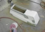
DSCN8227.JPG
Console repairs and fill.

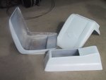
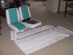
When the seat shells and console were returned, they were smooth and glossy and looked great. Further work on all three components will be required to finish them and this will be described on future postings.

IMG_0003.JPG
The console and seat shells as received from City Auto Body.
 

Kern Fischer

Seaman
Joined
Jun 24, 2013
Messages
51
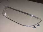
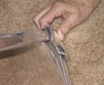
The original windshield was cracked from mounting screw stresses and had light scratching on the surface. This windshield was taken to a plastics molding shop and a new one was made, using the original as a pattern. This windshield has compound curves and requires a more complex mold than does a windshield with simple curves. The plastics shop did a very impressive job in getting the compound curvature precisely correct. They also polished the upper and lower aluminum channels that frame the windshield.

WSHLD1.JPG

The aluminum castings at the ends of the windshield did not fit well to ends of the upper and lower windshield frame moldings so they will be modified as required and chrome plated. This will be covered in a future posting.

WSEND4.JPG
 

Mark72233

Ensign
Joined
Jul 11, 2014
Messages
926
Kern that is beautiful work. Are you chroming the pieces yourself or is there a local place you are using. I have a couple of old pieces I need re-chromed but we don't have a local place that does that kind of work.
 

Kern Fischer

Seaman
Joined
Jun 24, 2013
Messages
51
Mark - The windshield frame parts are aluminum and the upper and lower rails were just polished. The end pieces are also aluminum but will have to be chrome plated after they are reshaped with filler material. The polishing/plating shop I use said that the aluminum casting and filler material look different after polishing so the chroming will be used to get a consistent look on those parts.

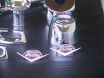
The polishing/plating shop I use was recommended to me by a builder of custom cars and hot rods. The shop is not cheap but his work is flawless. He is a one man shop so allow some time to get a project done. When I last visited, he was doing a project for the Budweiser horse drawn wagon. The photos below show many of the parts he did for my boat. Note in the closeup of the Glastron emblem that the detail, except for a small amount of the background texture, has been maintained.

CHRMHDWE3.JPG Brian's work on many of the parts for the 1963 JetFlite. The top tow eye has not yet been finished.

CHRMHDWE5.JPG

The person that does this quality of work is Brian Hahn at Superior Polishing in N.E. Illinois, near Chicago. His phone number is 847-264-0150.

I have no affiliation with Brian or his company other than as a very satisfied customer. I have a some additional parts to do and they will be going to Brian.
 

Kern Fischer

Seaman
Joined
Jun 24, 2013
Messages
51
City Auto Body finished their work painting the boat, parts, and trailer in August 2013 and we had to get the boat home. I found a car in my area that the owner of City was interested in buying. He offered to load the boat and trailer on his car trailer and put the parts in his truck and bring them to me. Then he would load the car and take it home. That worked out well for everyone. As a disclaimer, I have no business association with City Auto Body other than as a very satisfied client.

DSCN9859.JPG
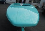
The foredeck as finished.

DSCN9904.JPG
All the items, except the motor, that were brought in the delivery.

On the trip over, he ran through a very heavy rain storm. The boat was not covered so the inside was rained upon. There were some access holes in the floor along with a slot that was cut by the first shop to route the control cables from the motor control back to the rear of the boat.

SIDE VIEW.JPG The delivery trailer. The tow vehicle is to the left and the boat was towed backwards.

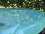
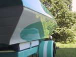
IMG_0008.JPG Foredeck reflections in the finished paint.

IMG_0010.JPG Side reflections.

While transferring the boat from the trailer to the work dolly it was stern down at one point. In this position I noted that water was running out of holes in the floor near the stern. This indicated that the cavities between the floor and the bottom were wet.

IMG_0019.JPG The hull resting on the work dolly.

I knew it would be almost impossible to get the cavities adequately dried so the hard decision was made to cut out the floor to expose the cavities for drying.

The rainstorm was a blessing in disguise. If I had not been forced to cut out the floor I would not have discovered some of the other issues that will be discussed in further posts.
 

Kern Fischer

Seaman
Joined
Jun 24, 2013
Messages
51
While the hull was being prepared and painted, some of the upholstery items were taken to Schober?s Auto Trim in Sandwich, IL (No affiliation). Schober?s was chosen because they have a good reputation in the custom car and hot rod show car community. When first approached with the request to trim a boat, their reaction was ?We do not do boats?. After I discussed that this was no ordinary boat and showed them pictures of a JetFlite, they agreed that it would be a fun, challenging project.

The trim will not be original in either colors or design as some or all of the materials are not easily available. The original seat cushions were solid aqua with an embossed design on the surface and this would not have been easily duplicated, nor was it as nice looking as possible. A vinyl color was chosen that closely matched the aqua color of the hull and a very pure white was chosen as the complementary color.

We started with the seat cushions, the instrument panel top, the foredeck center panel, and the side deck pieces. I discussed with them the design that I was seeking. The foam in the seat cushions was starting to sag so they replaced all the seat foam with a more dense version for better support. The seat cushions were two-toned with piping in the center to add more style and improve the appearance.

IMG_0033.JPG
A few of the finished interior trim items. The large panel in the front is the foredeck center trim. Behind that is the instrument panel top cover. The rolled up material at the left is the side deck trim.

Schober's also trimmed the previously exposed wooden surfaces of the seat cushions to improve the final look of the interior. The seat bottom cushions are removable from the shells and a pull handle was provided on the front of the cushion to lift it out of the shell. This was also changed for a much improved look and feel.
 

Kern Fischer

Seaman
Joined
Jun 24, 2013
Messages
51
It was decided to make gaskets for all the deck hardware to minimize damage to the newly painted surfaces and to provide a positive seal to prevent water and dirt from getting under the hardware. An old inner tube was obtained to make the gaskets. Various attempts were made to cut the gaskets to shape prior to attaching them to the hardware. This was especially difficult on the vents as the side walls are very thin and getting precise alignment and a good bond was almost impossible without a custom molded gasket that had a channel for the edges to sit into. Also, while trying to cut the rubber, it would be moving and stretching so precise cuts were difficult.

DECKGASKETS.JPG

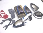
The above photo shows the final process that was developed to make the gaskets. The red items at upper left are cardboard patterns used to lay out the shapes and define hole locations. Then the gaskets were cut with the center areas being to the final shape desired and the outer edges being close but not on the precise edge of the part. Some overhang was left in the centers to provide for a silicone fillet. Mounting screw holes were punched in the parts, as shown next to the red patterns.

Then a bead of silicone was laid around the perimeter of the part where the gasket was to be bonded, as shown on the upside down vent in the lower center. The gasket was then mated to the part and the assembly was screwed down to a block of wood that had been drilled for this purpose. This holds everything in alignment and keeps the part and the gasket flat and tight until the silicone cures.

After the silicone has cured, the assembly was removed from the block and the excess rubber around the outside of the part was trimmed with a sharp knife, using the shape of the part to guide the knife. This allows the gasket to be trimmed right at the edge of the part for a neat, precise look. The trimming has started on the right side of the vent shown in the upper second from right position. The upper right vent shows the trimmed gasket bonded to the vent.

The lower right two items show the final trimmed versions of their gaskets. The cleat is quite easy, the stern light base slightly harder. The narrow oval around the stern light base is the trimmed edge that was removed from that part.

Silicone has several advantages for this process. It is relatively inexpensive, long lived, and a bead can be laid on the inside to provide larger amounts of surface area for adhesion. Another plus is that if the result is not satisfactory, it is easy to remove the gasket, strip off the silicone, and start over.
 

Mikeopsycho

Senior Chief Petty Officer
Joined
Feb 6, 2014
Messages
738
I like the gaskets! Good idea. Looks like it was a lot of frustrating work to get them just right, good for you! :)
 

sphelps

Supreme Mariner
Joined
Nov 16, 2011
Messages
11,436
I've never thought about gaskets for the deck hardware ... Pretty cool trick !
 

Kern Fischer

Seaman
Joined
Jun 24, 2013
Messages
51
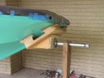
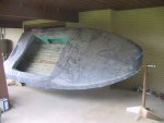
To facilitate working on the different sections of the hull, primarily inside, a rotisserie system was built so the hull could be easily rotated to different angles for access. Support posts were made at a height that was tall enough to allow full rotation without hitting the floor. Pivot fixtures were made for the front and rear of the hull. These pivot fixtures attach to the hull using studs through existing holes.

IMG_0030.JPG The bow pivot structure - mounted through the bow eye hole.

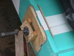
IMG_0029.JPG The stern pivot - mounted through the motor well drain hole.

To test the strength of the pivots, I added my weight to each end to simulate the condition where I would be inside the hull doing work. During this test, the working cradle, with plenty of padding, was under the hull to catch the hull if one or both of the pivots failed.

IMG_0027.JPG The hull supported on the two posts.

Fortunately, the hull mounting holes are close to the center of gravity and the hull rotates easily on the pivots. There is currently no provision for locking the pivots at a particular, desired angle, so supports are placed under the hull to prevent it from rotating when working on it.
 

Kern Fischer

Seaman
Joined
Jun 24, 2013
Messages
51
The pipe used for the pivots was ? inch I.D. The wooden adaptor pads were attached to the hull with threaded rod - 3/8 inch at the bow and ? inch at the stern. A steel pad (2 X 6 X ? thick) was used inside the bow to spread the load over more area to prevent internal damage.

The adaptor pads were built quite strong by gluing and screwing the parts together. They are approximately one foot square, again to spread the loads over a large area. When the hull is on the rotisserie, the threaded rods are in tension and one or two pads are in compression, depending upon the angle of the hull.

This is a smaller boat and the hull is not too heavy - approx. 500 pounds. When my weight and a few tools are added, the total does not exceed 700 pounds. Heavier boats will probably require larger and stronger components. The adaptors may also have to be more complex, depending upon where they are attached relative to the center of gravity of the hull.
 

Kern Fischer

Seaman
Joined
Jun 24, 2013
Messages
51
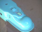
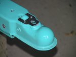
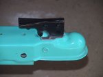
After getting the trailer back, some paint damage was noted on the top of the coupler where the latch slides on the surface, even though the trailer had not been used. This was predicted to be a potential rust spot so a stainless steel wear plate was made to protect the painted surface and prevent rust.

IMG_0013A.JPG Very little use and already the paint is damaged.

IMG_0017.JPG The stainless steel wear plate in place.

IMG_0015.JPG The assembled latch showing how it bears on the wear plate.

The next task on the trailer was to get the wiring routed for the rear lighting. The plan was to minimize the need to drill holes in the frame rails for retaining clips. To achieve that goal, the decision was made to route all the wiring inside clear, flexible, vinyl tubing and bond the tubing to the frame rails using clear silicone.

The trailer is a tilt bed with a pivot at the rear end of the tongue rail. Over time this pivot cannot be relied upon to always provide a good ground through the trailer frame, so a separate ground wire was routed from the vehicle plug back along each side to its respective taillamp. All wires were first pulled through the tubing that ran through the tongue rail. At the back of the tongue rail, the two sides were separated and run through separate tubing to the lamp on that side. At the rear of the tongue rail the two side harnesses were joined to the tongue harness using silicone seal and heat shrink tubing to obtain a water tight junction.

IMG_0001.JPG The junction from the front four wire harness to the side three wire harnesses. This junction was pulled forward into the tongue beam.

IMG_0020.JPG The harness exit from the rear of the tongue beam.

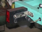
Each side harness was then routed along the top inside corner of its respective frame member and bonded to the painted surface with clear silicone. Where necessary to penetrate a frame rail, grommets were used to protect the vinyl tubing and to seal off the bare metal where the hole was drilled. The taillamps will be immersed when launching and retrieving the boat so Weather Pack connectors are used to join the lamps to their respective harnesses. All lamp wiring and brackets were then covered by the lamp fairings.

IMG_0019.JPG
The wire routing on the forward portion of the trailer frame. The clear silicone holds the harnesses in place without damaging the paint. All frame penetrations are grommeted.

IMG_0025.JPG The rear frame wire routing.

IMG_0010.JPG The lamp connection using Weather Pack connectors. All possible sources of water entry or retention are sealed with silicone.

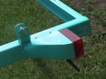
IMG_0015.JPG
The lamp fairings improve the appearance and hide and protect the wiring.

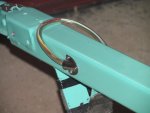
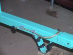
At the front of the tongue rail, a neat exit for the harness was created by drilling a hole in the side of the rail for the harness to pass through. Then a small PERKO scoop was screwed into place to cover the opening and silicone seal was used to close any gaps. Two small stick-on clips were attached to the opposite side of the tongue rail to neatly stow the harness end when it is not being used.

IMG_0036.JPG The harness exit on the left side of the tongue rail.

IMG_0033.JPG The front harness in the stowed position.
 

Kern Fischer

Seaman
Joined
Jun 24, 2013
Messages
51
As previously mentioned, during delivery water entered the cavities under the floor and resulted in the decision to cut out the floor to be able to dry the cavities.

In retrospect, it is good that the water forced this decision. Inspection of the structure under the floor showed that the stringers were not rotted but there were other structural issues that needed correction, primarily failed bonding of fiberglass resin to wood parts so that the stringers were no longer connected solidly to the bottom of the hull. The stringers were also broken in several places where stresses were concentrated due to holes or notches. During later years of usage I noted that when hitting waves the whole structure would shake and did not feel solid. I could now see why - the floor and hull bottom were no longer well connected and could move separately in a vertical direction.

While the boat is on the cradle, the stringers will be replaced. The floor was cut out above the starboard outboard stringer forward to the floor step. The cavities were partially filled with Great Stuff foam that Starboard Marine had squirted into the spaces through floor openings per my request. The foam filled most of the volume but still left some voids where water could collect, so it is not the most effective method of adding flotation.

During floor removal some plastic sleeves containing foam balls were found in the cavities. Starboard had mentioned that they also found some of these sleeves. They were evidently placed in the floor cavities at original build as a means of providing flotation. However, the volume of foam was much too small to provide enough flotation to keep the boat afloat if swamped.

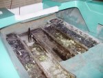
The initial construction of the fiberglass caps over the stringers was not well done and there were gaps in the fiberglass. Over time, the stringer wood had shrunk and the stringers no longer fit tightly within the fiberglass caps.

IMG_0015C.JPG
The starboard outboard stringer as originally installed.

The fiberglass cap for the stringer was cut away and the stringer removed easily as it was not bonded to the bottom. The stringer had no rot but had broken at some weak areas near the rear of the boat. The poor construction of the stringer caps would have allowed any water to get to the stringers. Probably what saved these from rot was that early on I closed the drain holes in the bilge well so water could not get into the underfloor area.
IMG_0024A.JPG
Looking aft at the crude initial installation. The loose piece at the end of the starboard inboard stringer is a portion of the fiberglass cap that was easily torn loose from the stringer and the bottom.

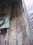
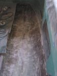
After removal of the stringers, the inside of the bottom was sanded smooth to remove all the old material from the fiberglass stringer caps and to provide a good surface for bonding the new stringers and the fiberglass strips that reinforce the stringer to bottom joint. The inner bottom surface was not perfectly straight so some sanding was required to get the stringer to fit reasonably well. The epoxy resin will adequately fill the remaining small gaps between the stringer and bottom.
IMG_0001.JPG
The track where the starboard outboard stringer laid on the bottom. It was not bonded to the bottom and depended only upon the fiberglass cap to provide bottom strength.
IMG_0011B.JPG
The bottom surface after grinding away all the old stringer cap material.

The wood chosen for the new stringers was clear poplar. Oak was another possibility. The outboard stringers were made from 1 X 3 and the inboard stringers from 1 X 4 finish sanded boards. Careful selection was required to get boards that were as straight as possible.

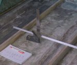
The old stringers were not usable as patterns as they were broken in a few places and did not fit the bottom contour reasonably closely. The outer stringer contour was defined by measuring from the inner bottom surface to the defined floor level at one foot intervals along the stringer location. Then the floor thickness (1/2 inch) was subtracted to find the height of the stringer at that location. These height dimensions were then transferred to the stringer board and the contour was cut.
IMG_0005.JPG
Measuring the height of the starboard inboard stringer at intervals along its length to create the contour required. The starboard outboard and port inboard stringers are shown already installed.

After consulting with a knowledgeable resin person at Jamestown Distributors, it was decided to use epoxy resin on the rebuild, even though it is more expensive and is not typically used in boat construction. It is believed that the epoxy will provide a superior bond to the various materials being used in rebuilding.

After removal of the stringer, a T-beam was placed under the stringer location on the starboard side of the hull. The port side was supported by two jack stands. The T-beam was put into place to provide a straight surface to support the bottom during fitting and bonding of the new stringer. The stringers were replaced one at a time using this method.

IMG_0013A.JPG The T-beam in place under the position of the starboard outboard stringer.
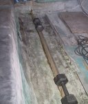
IMG_0002A.JPG
The starboard outboard stringer being bonded to the bottom. The weights were used to hold it tightly against the bottom surface while the T-beam kept everything straight.

The inner stringers went forward under the raised floor at the front of the hull. That section of floor was left in place and I did not want to remove the stringers, even though they could probably have been pulled out from under the floor. They hydrodynamic loads in that forward area are not as great as further astern so the existing structure was felt to be adequate.

The loads on the stringers are upward and by angling the cut, the loads on the new stringer will be transferred into the stub of the old stringer. To strengthen the joint between the new and old sections, small sections of ? inch plywood will be bonded to each side at the stringer joint. The fore and aft ends of these plywood pieces are ground at an angle to provide a good blend for the fiberglass cloth that will be laid along the sides of the stringer to add to the floor/stringer strength. Any gaps in the fit between the stringer ends and the plywood pieces will be filled with epoxy resin.
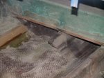
IMG_0016.JPG The angle cut at the end of the inboard stringers just aft of the raised floor in the bow area.
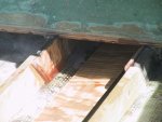
IMG_0014.JPG The inner plywood reinforcements at the joint between the new and old inboard stringers. Outer reinforcements will also be added and any gaps filled with epoxy resin. Also shown is the top plywood stiffener/filler for the keel channel.

Surprisingly, the hull had no keel board and depended only upon the stiffness of the hull structure to hold the keel alignment. The boat rests on keel rollers on the trailer, so it was decided to add some extra strength to the keel and also fill the channel to provide a flat area for easier fitting of the flotation foam. Strips were made from the stringer scraps, laid into the keel channel and bonded in place. The bottom layer is a narrow strip, the second layer is two wider strips, and the top layer is plywood. End joints were staggered. The side gaps will be filled with fiberglass cloth strips and resin to form a solid core for the keel channel.
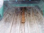
IMG_0016.JPG All the new stringers are bonded in place and the reinforcing strips for the keel channel are being laid into position. Cavities in the keel channel around the wood strips will be filled with epoxy resin to create a very stiff keel area.
 

Woodonglass

Supreme Mariner
Joined
Dec 29, 2009
Messages
25,924
Sooo you bonded the wood stringers directly against the fiberglass hull???:eek:
 

Kern Fischer

Seaman
Joined
Jun 24, 2013
Messages
51
That I did. Did I commit a serious boat building faux pas?
I also bonded wood to the fiberglass for the foredeck structure and for my transom rebuild, which I will describe in future posts.
 

Woodonglass

Supreme Mariner
Joined
Dec 29, 2009
Messages
25,924
Uhmmm Yeah, It's really not a good idea for the wood to be placed directly in contact with the glass. It creates 'Hard Spots" and this in turn could cause the glass/gelcoat to crack and craze in time. The PRO's here on the forum, for years have recommended always bedding the stringers in thickened resin or Construction adhesive or various other methods to keep the wood core from coming into direct contact with the hull. Also Poplar is not one of the best choices of wood for marine use. However it really doesn't make that much difference if you do a really good job of glassing then there's not much of a chance of water ever getting to the inner core any way. This forum usually recommends using Plywood due to it's strength and water resistance characteristics. I'll be interested in following up to see if you have problems with the bottom of the hull. Since she's painted and not gelcoated you may be A-OK. I will say that back in the day a lot of the boats came out of the factories with the wood stringers laying directly on the hulls. But we did see the effects of this too!!! Hopefully you won't Transoms are bonded directly to the outer skin but the border around the deck is usually shielded by a gap of thickened resin to guard against the same thing.
 

Kern Fischer

Seaman
Joined
Jun 24, 2013
Messages
51
Woodonglass - thank you for your comments regarding the construction I used. You clarified my question regarding why the stringers were not bonded to the bottom. I assumed it was some issue related to production costs or expediency.

As a mechanical engineer, I am constantly experimenting with different methods, materials, or devices to accomplish projects. Some of the experiments create breakthroughs and good results and some crash and burn. Every one is part of an ongoing education. I am an automotive engineer, not marine, so am not familiar with industry practices in the marine field and my experiments may not be according to standard practice.

I also noted that the wood supports that were installed under the foredeck were not bonded directly to the fiberglass and were attached using strips of fiberglass at several places around the supports, with cardboard shims between the supports and deck! The fiberglass strips were bonded to the supports and the underside of the deck. This did not prevent the deck from flexing from the weight of crawling on it and spider cracking developed over time. The new deck structure will be posted later and it is very rigid.

I chose poplar for the stringers because it was readily available in the sizes I needed, has nice straight grain, and I knew I would be preventing it from being exposed to water. I had not even thought about using plywood, although, as you note, it would have been a good choice.

I assume that the ?hard spots? you reference create the cracking/crazing due to flexing of the fiberglass between these hard spots. I am hoping to minimize the flexing of the bottom by filling the cavities between the bottom and floor with the rigid pink foam, bonded in place. When completed, there will be no voids for water retention and the floor and bottom will be a rigid structure. The stringers will be carefully and completely encased in resin so no water can get to them. I would not make a good production worker as I am too slow and methodical.

I chose to put the foam in the bottom cavity to add rigidity, eliminate water entry, and aid flotation of the hull. I am investing so much time and money into this boat that I never want it to sink - ever! To that end, I will be adding a total of about 15 cubic feet of flotation foam wherever possible in the hull, concentrating as much as possible toward the stern. Future posts will show the installations of the foam.
 

Woodonglass

Supreme Mariner
Joined
Dec 29, 2009
Messages
25,924
Flotation Foam is a good thing and will also add to the rigidity of the hull but the hull will still flex when you hit waves and wakes. Over time I fear that since the stringers etc. are in direct contact with the hull you may develop some issues. Only time will tell. If she were a larger craft, there would be more of a concern.
 
Top