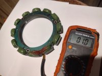
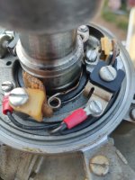
hard to say for me anyway maybe Racerone can comment .. any burn marks are not very good and may indicate arcing althoug the stator is an AC generator not HV as in the ignition coil.
arcing may have taken place from a close by " hot spot" due to a " better" ground proximity than plug gaps. other than replacing suspect parts the only way to suppress arcing is what use to be called HV silicon or dorona dope which was more common in older TVs .. to stop arcing from the HV coils. looked it up but did not see such productsavailable...seems they call it " grease now" maybe it could help...stop any arcing
I will let racerone or other experts comment on this one.
but here is a comment from an intelligent source...
Q:....How can I stop arcing across 2 parts of an outboard ignition system does silicone corona dope exist like in the old TV days
Yes — what you remember from the old TV days
does still exist, and your instinct is right… but with outboards, you have to be careful:
arcing is almost always a symptom of a fault, not just an insulation problem.
 Why arcing happens (same physics as CRT TVs)
High-voltage ignition (20–40 kV) will
always take the easiest path to ground. If it’s jumping somewhere it shouldn’t, it means:
- Insulation is compromised (cracked coil, wire, boot)
- Moisture or contamination is present
- Gap somewhere is too large (plug gap, bad connection)
- Internal component failure (coil, condenser, etc.)
For example, cracked coils or damaged insulation will let voltage leak or arc externally .
 Proper fixes (ranked from “correct” → “temporary”)
1. Fix the root cause (best solution)
Do this first — otherwise any “dope” is just masking:
- Inspect coil housing for cracks or carbon tracking
- Replace old or brittle plug wires
- Check boots for cuts or poor seating
- Clean and dry everything (moisture is a big trigger)
- Verify spark plug gap and condition

Even a slightly loose terminal can raise voltage enough to force arcing elsewhere
2. Repair insulation (acceptable in some cases)
If the problem is clearly
minor insulation damage, you can seal it:
- Liquid electrical tape (neoprene dip)
- RTV silicone (high-voltage rated)
- Heat-shrink tubing (best for wires)
This is actually used in outboards:
sealing cracked coils or wires with insulating coating can restore insulation and stop leakage
3. Dielectric grease (limited use)
- Good for sealing out moisture
- Helps prevent tracking on boots
- BUT it is an insulator, so:
- use only a thin film
- never fill connectors (can cause misfire)
 What about “corona dope”? (your main question)
✔ YES — it still exists
- Still sold as “corona dope” / insulating varnish
- Used in:
- high-voltage electronics
- transformers
- coil windings
Typical modern equivalents:
- Insulating varnish
- Glyptal / red enamel
- MG Chemicals “Super Corona Dope”
 BUT for outboards:
It’s
not the preferred fix because:
- Outboards vibrate → coating cracks
- Salt/moisture → creeps under coating
- If arcing is strong, it will burn through again
- Usually indicates a failing coil or lead anyway
In CRT TVs it worked well because parts were static and enclosed
On an outboard, it’s usually
temporary at best
 Practical recommendation (what I’d do)
If you see arcing:
Step-by-step:
- Run engine in the dark → locate exact arc point
- Clean + dry area thoroughly
- Inspect for:
- cracks
- carbon tracking (black lines)
- If damaged:
- If minor:
- apply liquid tape or RTV silicone
- Use dielectric grease only at boots (lightly)
 Bottom line
- ✔ Yes, corona dope still exists
 But it’s not a real fix for most outboard ignition arcing
 Best fix = eliminate the reason voltage is escaping


")