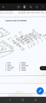
Just finishes all my painting so getting out board back together. I need some help with putting things back on as I lost all the photos I took before I took it apart. Doing the best I can with the diagrams in the repair manual but I'm a bit stuck on the hose routing.
It seems each of the 4 bypass covers on the block have 2 hose nipples. I believe 1 of these by pass covers nipples goes to 1 of the 4 nipples on the inlet manifold. I assume to the corresponding cylinder for fuel by pass?
What is the purpose of fuel bypass?
What is the other nipple on each by pass cover for? Does any one have any photos or diagrams?
Thanks
Going to answer my own question here incase someone finds it in future...
The purpose of the bypass is because the 2 stroke oil collects in the crank case and puddles in various places. The recirculation circuit is to suck that oil out of the inlet and into the bypass covers where it will enter the cylinders directly on the inlet stroke and burn it up.
This means these little check valves allow air/fuel/oil out of the inlet, but not in. It appears from the very hard to follow diagram in one of the manuals that it is routed as follows:
Each bypass cover has 2 nipples, one is for the primer solenoid, and one is for recirc (I don't think it matters which nipple you use on the cover). Cylinders and numbered from top to bottom 1 (Starboard), 2 (port), 3 (Starboard), 4 (Port). I'll also number the recirc check valves on the inlet from top to bottom, 1, 2, 3, 4. It appears they connect as follows:
Cyl 1 bypass cover to Check Valve 3
Cyl 2 bypass cover to Check Valve 4
Cyl 3 bypass cover to Check Valve 1
Cyl 4 bypass cover to Check Valve 2.
For the primer solenoid there is one inlet and 2 outlets. Each outlet goes to a T-piece (1 per bank), and from the T-pieces to the bypass cover nipple.
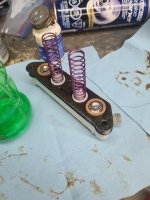
The nipple of one of the check valves was snapped. It seems the plastic ones have been replaced by metal ones now which aren't cheap. I just epoxied by host onto the remainder of the check valve and it seems fine. For any check value you should check correct operation. Stick the nipple in your mouth and suck, you should feel air pass. Blow and the air should not pass. If it's stuck you could soak it overnight in vinegar to try to dissolve any crud and free it up.

I think this diagram is very poor. Its very hard to follow where each recirc hose goes. Also it shows each bypass cover as only having one nipple and the primer hoses going to between the carb barrels. On mine each bypass cover has 2 nipples and it one of these is where the fuel from primer goes.
Other updates on previous questions...
Slight bend in shift rod didn't matter too much, even when it was in and it was pushing against the back, once the throttle lever was connected it held it place and appears to shift just fine.
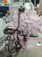
For wiring things pretty much fit where they fit. The most important thing is when connecting up the coils, each powerpack has an Orange and an Orange/Blue wire. I believe the Orange/Blue wire goes to top (Cyl 1 and 2) coils and the Orange to lower (Cyl 3 and 4) coils. Some wiring diagrams contradict this and some have obvious errors, but this seems to be the consensus.
For videos showing the engine and where things go I used these videos:
One thing I learnt the hard way is the shift lever should be inserted in the inlet before you install the powerhead. There is a bracing on the lower cowling cover which will prevent it being inserted after. I had to remove the inlet manifold after the powerhead was on, so I could insert it (I had thought about cutting the cowling, but removing the inlet is fairly easy provided you have a spare gasket).
Very close to trying to start this engine now. Slowed down by a snapped nipple on fuel pump which I've bodged with epoxy and a metal tube until new one arrives.