How to install a SMARTCRAFT system

Status
Not open for further replies.

B&C

Recruit
Joined
Apr 22, 2012
Messages
1
Smartcraft Issue

Smartcraft Issue

This is a great thread. I wish I would have found it sooner. I'm having an issue with my smartcraft gauge. It is reporting a data bus error. It was intermittent about 2 years ago and last year it started reporting the error continuously.

My setup:

2005, 200HP Optimax, Single Gauge, Cable with built in resistors. 5 wires are in the connector on the engine side. Red/black, black, ?, blue and white.

Details:
The tach works but floats with about a 300 rpm range around the true rpm.

I've pulled all the connectors looking for corrosion and haven't found any. I'm not sure where the ground lug is but all the grounds I've found on the engine seem to be clean and tight (It seems like a ground issue??). I've ohm'ed out the cable, with continuity on all the pins.

I'm to the point of trying out some expensive parts and I want to get some advise before I go there (Gauge, cable, engine controller). Is there a way to isolate the issue? What should I be looking for?:confused:

Thanks in advance for your input!!

-CC
 

henryj

Cadet
Joined
Mar 21, 2012
Messages
17
Re: Smartcraft Issue

Re: Smartcraft Issue

I really dont know enough to help you. Hopefully Rotorfixer will see your question and respond.
 

henryj

Cadet
Joined
Mar 21, 2012
Messages
17
Re: Smartcraft Issue

Re: Smartcraft Issue

I read a thread prior which stated the harness should be secured every 18 inches and should not hang straight from the gauge. Did you try contact cleaner?
 

henryj

Cadet
Joined
Mar 21, 2012
Messages
17
Re: Smartcraft Issue

Re: Smartcraft Issue

I came across a service bulliten which might save some headaches. Trying to put as much info as I can find so as to help anybody in the future.
Service bulletin No. 2002-15 basically states that some harnesses with resistor ends were assembled incorrectly. There are a blue and white wire that had their positions swapped during manufacturing. The blue wire should be at the corner end of the harness and the white should be just inside of it. Here is a pic of a correct harness.
sc100harness.JPG
 

meo

Recruit
Joined
Apr 24, 2012
Messages
3
Re: How to install a SMARTCRAFT system

I have a 2012 princecraft starfish dlx sc with a 40hp elpt mercury outboard.
I would like to install the mercmonitor on it but i don't know which part i need to install it.
There are too many different part number for the assembly.

My second question is do i have to plug it into the GPS antenna or can i just plug it on the engine.

Can anyone help me out ?
 

toolman99

Seaman Apprentice
Joined
Aug 22, 2010
Messages
45
Re: How to install a SMARTCRAFT system

just a few pics of the fuel oil paddle connector on a current FourStroke as well as the Digital trim connector
HPIM1914.jpg This is the connector and using the weather cap ( just the other half of the connector with rubber plugs where the wires go) I inserted a pink wire from the sender on tank 1 and a ground to the black/stripe wire using male pins from these cheap delphi type connectors on ebay http://www.ebay.ca/itm/Kit-1-5mm-Ca...717832?pt=Car_Audio_Video&hash=item20c4cced08

here is the trim connector HPIM1917.jpgI have a conversion kit coming that connects here to give digital trim as well as water pressure and pitot pressure, is you don't need the pressure senders you can save a few bucks and just buy the digital sender vs the whole conversion kit and add the 3 wires required as I did with the fuel sender connection. I have instructions for the conversion kit install but I have to figure out how to upload pdf files
 

toolman99

Seaman Apprentice
Joined
Aug 22, 2010
Messages
45
Re: How to install a SMARTCRAFT system

Here is the text from the pdf instructions to install the trim conversion kit pn 889250K01 SMARTCRAFT SENSOR CONVERSION KIT

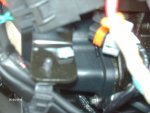
75/90/115 EFI 4-STROKE NOTICE After completing installation, place these instructions with the product for the owner's future use. NOTICE This document is written to aid our dealers, boatbuilders, and company service personnel in the proper installation or service of our products. Persons who are not familiar with these or similar products produced by Mercury Marine, and who have not been trained in the recommended servicing or installation procedures should have the work performed by an authorized Mercury Marine dealer technician. Improper installation or servicing of the Mercury product could result in damage to the product or personal injury to the installer or persons operating the product. Components Contained in Kit a b c d e f ghijk 21766 Ref. Qty. Description Part Number a 1 SmartCraft sensor harness assembly 84-889250T01 b 1 Water pressure sensor assembly 881879A20 c 1 Pitot sensor assembly 881879A16 d 4 Cable tie (8 in.) 54-816311T e 1 Tubing - 10 in. x 5/32 in. outer diameter 32-859785 71 f 1 Trim position sensor 896688001 g 1 Fitting assembly 22-896094A01 h 1 Elbow fitting 22-59351 i 1 Adapter fitting 22-859731 j 1 Female molded cap 13540 90-889250003 MAY 2010 ? 2010 Mercury Marine Page 1 / 8 SMARTCRAFT SENSOR CONVERSION KIT Ref. Qty. Description Part Number k 1 Connector clip 54-879962 SmartCraft Sensor Conversion Kit Installation 1. Remove the 8 pin digital input connector from the electrical plate, located on the rear starboard side of the engine below the relays. Remove the cap and mount clip from the connector. NOTE: Remove any remaining pieces of the mounting clip from the electrical plate. 21770 2. Attach the connector clip provided with the kit to the 8 pin SmartCraft harness connector. 3. Connect the SmartCraft harness to the 8 pin digital input connector on the engine harness. Mount the connectors to the electrical plate. a -SmartCraft harness connector b -Engine harness digital input connector 21772 4. Route the SmartCraft harness up the rear starboard side of the engine and cable tie the harness to the lower fuse breakout harness. ba Page 2 / 8 90-889250003 MAY 2010 SMARTCRAFT SENSOR CONVERSION KIT 5. Install the pitot sensor into the lower hole on the electrical plate above the starter solenoid. The pitot sensor has a blue dot, and is stamped with the number 881879-11. ab a -Cable tie securing SmartCraft harness to lower fuse breakout harness b - Pitot sensor assembly 21785 6. Install the block water pressure sensor into the upper hole on the electrical plate above the pitot sensor. The block water pressure sensor has a white dot, and is stamped with the number 881879-12. ab a -Pitot sensor assembly b -Block water pressure sensor 21790 7. Remove the connector caps from the two 3 pin connectors on the SmartCraft harness. Plug the 3 pin connector containing the white/green wire into the water pressure sensor, and the 3 pin connector containing the white/orange wire into the pitot sensor. 8. Pull the pitot tube out of the rigging grommet located at the front of the engine and route the tube down the starboard side of the engine. Cut off the pitot tube connector. 21867 90-889250003 MAY 2010 Page 3 / 8 SMARTCRAFT SENSOR CONVERSION KIT 9. Route the pitot tube under the oil filter and along the red power wires. Guide it through the loop of power wires that protrude from the starter solenoid. a -Pitot sensor b -Pitot tube c -Starter solenoid power wires cba 21797 10. Before inserting the adapter fitting into the pitot tube, ensure the pitot tube was cut short enough to avoid rubbing on the cylinder head. Insert the adapter fitting into the pitot tube. Connect the pitot tube to the pitot sensor. IMPORTANT: If the length of the pitot tube is too long, excessive wearing may occur. To avoid pitot tube failure, ensure the pitot tube does not rub against the side of the cylinder head. abc a -Pitot sensor assembly b -Pitot tube c -Hose rubbing against cylinder head 21837 Page 4 / 8 90-889250003 MAY 2010 SMARTCRAFT SENSOR CONVERSION KIT 11. Trim the motor up so the trim sensor is fully exposed and engage the tilt support lever. Remove the analog trim sensor. a -Analog trim sensor a 22076 12. Disconnect the trim position sensor brown/white wire bullet connectors located in front of the fuel system module (FSM) in front of the engine. Seal the engine brown/white wire bullet connector with the cap supplied with this kit. abc21860 a -Brown/white wire b -Air filter c -Fuel system module 13. Pull the trim position sensor brown/white wire out of the adapter plate grommet. 14. Remove the screw securing the wire retainers mounted on the starboard transom clamp bracket and pull out the trim position sensor lead. 21866 15. Install the digital trim position sensor. The wire leads must point down, and the rotating armature of the sensor must be properly aligned in the sensor mount. 16. Guide the trim position sensor wires through the hole in the starboard clamp bracket. Trim the engine up completely and pull the wires taunt. 90-889250003 MAY 2010 Page 5 / 8 SMARTCRAFT SENSOR CONVERSION KIT 17. Insert the trim position sensor wires into the wire retainers. Secure the wire retainers to the starboard transom clamp bracket with a screw. Tighten the screw securely. 21866 18. Push the trim position sensor bullet connectors through the adapter plate grommet. If the grommet should come loose, lubricate the grommet and push in until seated. 21868 Description Where Used Part No. 36P80 Rubber Lubricant Adapter plate grommet Obtain Locally 19. Disengage the tilt support lever. Trim the engine to its extremes and check for trim position sensor wire lead interference. Adjust the wire leads if necessary to avoid interference. 20. Run the sensor leads under the oil filter and up along the water hose that connects to the thermostat housing. 21. Remove the bullet connector plugs from the three bullet connectors located on the SmartCraft sensor harness. 22. Connect the trim position sensor bullet connectors to the SmartCraft sensor harness; black to black/orange, yellow to yellow, and light blue to purple/yellow. Secure the sensor leads and SmartCraft sensor harness to the existing engine harness. a a -Trim position sensor bullet connectors 21869 23. Use a 4 mm Allen wrench to remove the brass plug located under the starter motor on the engine block. NOTE: To aid in loosening the brass plug, tap on the end of the Allen wrench with a hammer. Page 6 / 8 90-889250003 MAY 2010 SMARTCRAFT SENSOR CONVERSION KIT 24. Separate the two pieces of the fitting assembly provided with the kit. Assemble the pieces to the elbow fitting as shown, and thread it into the block. aab a -Fitting assembly b -Elbow fitting 22101 25. Tighten the block water reservoir tap using a 16 mm (5/8 in.) and 14 mm (9/16 in.) wrench on the brass fittings. Use a 13 mm (1/2 in.) wrench to tighten down the stainless Legris fitting. 21871a a -Block water reservoir tap 26. Install the polyurethane tubing over the water hose, and into the block water pressure sensor and block water reservoir tap. IMPORTANT: Do not allow the polyurethane tubing to contact the cylinder head, as chaffing from the cylinder head may damage the tubing. abcde21875 a -Block water pressure sensor b -Pitot sensor c -Polyurethane tubing d -Block water reservoir tap e -Pitot tube 90-889250003 MAY 2010 Page 7 / 8 SMARTCRAFT SENSOR CONVERSION KIT Mercury, Mercury Marine, MerCruiser, Mercury MerCruiser, Mercury Racing, Mercury Precision Parts, Products of Mercury Marine Mercury Propellers, Mariner, Quicksilver, Alpha, Axius, Bravo One, Bravo Two, Bravo Three, K-Planes, W6250 Pioneer Road MerCathode, OptiMax, Precision Pilot, Pro Max, SeaCore, Skyhook, SmartCraft, Sport-Jet, Total Command, Verado, VesselView, Zero Effort, Zeus, #1 On The Water, M with Waves logo, Mercury with Fond du Lac, WI 54936-1939 Waves logo, and SmartCraft logo are all registered trademarks of Brunswick Corporation. Mercury Product Protection logo is a registered service mark of Brunswick Corporation. Page 8 / 8 90-889250003 MAY 2010
 

henryj

Cadet
Joined
Mar 21, 2012
Messages
17
Re: How to install a SMARTCRAFT system

I am at wits end. I cannot get comm between motors and SC1000 gauges. Going to take it to a dealer. Called merc and was told I have everything correct from what I have told them.
 

toolman99

Seaman Apprentice
Joined
Aug 22, 2010
Messages
45
Re: How to install a SMARTCRAFT system

Received my smartcraft conversion kit for 75-115 FourStrokes today, couldn't wait to get it installed and tested. All went well, great instructions but here are my pics and notes to supplement. HPIM1919.jpgHPIM1920.jpg here are the contents of the kit, digital harness, digital trim sender, 2 pressure senders, tubing, fitting, plugs and tie wraps HPIM1921.jpgHPIM1922.jpgHPIM1923.jpg business end of the harnessm 3 wires for the trim sender and 2 connectors for the pressure senders
 

toolman99

Seaman Apprentice
Joined
Aug 22, 2010
Messages
45
Re: How to install a SMARTCRAFT system

HPIM1924.jpgHPIM1925.jpg lower rear starboard side, capped connector for the digital sender harness. The weather cap is secured to the plate with a small grey connector. that one can be cut off to remove the cap and a new one is included in the kit.

HPIM1926.jpg open holes in the plate for the pressure senders
 

Attachments

  • HPIM1927.jpg
    HPIM1927.jpg
    139.6 KB · Views: 7
  • HPIM1928.jpg
    HPIM1928.jpg
    131.4 KB · Views: 7

toolman99

Seaman Apprentice
Joined
Aug 22, 2010
Messages
45
Re: How to install a SMARTCRAFT system

HPIM1930.jpg Harness and 2 pressure senders installed
HPIM1931.jpg Stock analog trim senderHPIM1932.jpg
HPIM1934.jpg trim sender tab fits in this screw slot which rotates as the engine moves up and down HPIM1935.jpg Digital sender with tab
 

toolman99

Seaman Apprentice
Joined
Aug 22, 2010
Messages
45
Re: How to install a SMARTCRAFT system

HPIM1936.jpg trim wires entering the bottom of the cowling, grommet fremoved to thread the wires HPIM1937.jpg trim cable secured on bracket as the originalHPIM1938.jpgHPIM1939.jpg wiring routed, ready to re-install the grommetHPIM1940.jpg
 

toolman99

Seaman Apprentice
Joined
Aug 22, 2010
Messages
45
Re: How to install a SMARTCRAFT system

HPIM1941.jpg grommet installedHPIM1942.jpg wires routed and tested to clear throughout trim/tilt range
HPIM1944.jpg water pressure fitting HPIM1945.jpg water pressure tubing installed in the sender
 

Attachments

  • HPIM1943.jpg
    HPIM1943.jpg
    146 KB · Views: 2

toolman99

Seaman Apprentice
Joined
Aug 22, 2010
Messages
45
Re: How to install a SMARTCRAFT system

HPIM1947.jpg stored pitot tubing on the lower front port side by the engine harness pass through grommet
HPIM1949.jpg pressure senders connected to water pressure tubing and pitot tubing
 

toolman99

Seaman Apprentice
Joined
Aug 22, 2010
Messages
45
Re: How to install a SMARTCRAFT system

Again, money saving tip for anyone who wants the digital trim sender but can do without water and pitot pressure, just use the weather cap on the existing connector to install 3 wires to the black, lt blue and yellow connections and buy just the digital trim sender for about half the cost of the whole kit.
all in all a smooth, easy install with good clear instructions, took about an hour even with taking pics . all that's left after that is to calibrate the trim sender in the merc monitor settings menu
 

rickdb1boat

Supreme Mariner
Joined
Jan 23, 2002
Messages
11,195
Re: How to install a SMARTCRAFT system

Excellent writeup! One day I will install that kit on my 07' 90HP. Thanks..
 

salmon troller

Recruit
Joined
Apr 29, 2012
Messages
5
Re: How to install a SMARTCRAFT system

As others have stated, this thread is a fantastic source of info. It's really filled an information void regarding SmartCraft. I think I read every post under this thread and I still have a question. I removed the Tach that I assume is analog with my 2003 Optimax 135. What did you guys do with the wires that were on the original Tach? I wanted to keep them somewhat intact in case I end up selling the boat in the future. It looks like it was wired in succession with some of the other gauges and now my fuel gauge & trim (non SmartCraft) aren't working. Should I cut off the connectors and wire nut the groups that were previously together? Thanks Scott

I guess I missed it on the first page!
 

captkrok

Recruit
Joined
May 9, 2012
Messages
1
Connecting Fuel Sender and fuel/oil/paddle harness?

Connecting Fuel Sender and fuel/oil/paddle harness?

This is regarding the 859743T03 fuel/oil/paddle harness with the 6-pin connector in one end and 4-pin connector in the other. Do I connect the 4-pin end to the plug just along side the smartcraft can-bus connector at the engine side (thats a 100hp, fourstroke, 2010mod by the way)? If so, how do I connect my fuel sender to the 6-pin connector in the other end of the harness? I have a wema S3 fuel sender that is connected to a fuel gauge from teleflex. I`m not sure that this sender will work with the smartcraft(digital)? I only wish to get the fuel info to the sc1000 monitor.

Regards Thomas
 

toolman99

Seaman Apprentice
Joined
Aug 22, 2010
Messages
45
Re: Connecting Fuel Sender and fuel/oil/paddle harness?

Re: Connecting Fuel Sender and fuel/oil/paddle harness?

Hi, I'm not certain about the sc1000, but I just wired my 2011 90hp 4stroke to my stock fuel sender for my mercmonitor gauge. check down about 12 posts to 286. all I did was wire ground and the pink wire from the fuel tank into the connector using the existing weather cap on the connector. you could just connect your cable and cut off the unused wires and connector and stow them or return your adapter cable and do as I did.
 
Status
Not open for further replies.
Top