Force 125 tilt/trim pump bypass valve

dancewithme951

Petty Officer 3rd Class
Joined
Jan 27, 2014
Messages
75
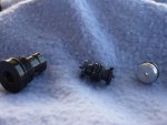
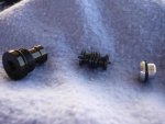
I screwed up a bit when installing a new tilt/trim pump on my Force 125 motor. BTW the pump/motor was from JB Electric TRM8000 pump. Pump/motor went on fine but as I commenced the bleeding process immediately the oil seen through the fill hole became milky. So I thought it best to just try to drain all prior oil and opted to try using the bypass valve instead of disconnecting one or more of the hydraulic lines. I carefully screwed out the bypass valve and the second component in the assembly came out. I set that and the piece with the allen head aside to allow more flow. A minute or so later I saw a piece on the ground that must have come out without my noticing it. Problem I don't know in what position that piece should be when reassembling. It's the aluminum part with the o ring on the right. Do you have any idea how these should be reassembled. I don't want to screw this brand new pump up by trying to reassemble it incorrectly.

Here are pictures of the parts: P1010553.jpgP1010554.jpg
 

pnwboat

Rear Admiral
Joined
Oct 8, 2007
Messages
4,251
Re: Force 125 tilt/trim pump bypass valve

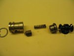
Here is the same assemebly from an earlier style. The aluminum piece on the left is the equivalent of the plug with the allen wrench fitting on your motor. There is a small hexagonal shaped valve with a small "O" ring on the nipple and a spring that holds it sealed. In the picture, the hex valve with the nipple and the spring are reversed both in order of assembly and orientation. Looks like you are missing those items..... the hex shaped valve and spring.

check valve1.JPG

Without those two pieces, the tilt/trim will not work.
 
Last edited:

Frank Acampora

Supreme Mariner
Joined
Jan 19, 2007
Messages
12,004
Re: Force 125 tilt/trim pump bypass valve

The black center piece is the shuttle valve. it goes into the valve body first. When you activate the pump, pressure shifts it to one side, opening that check valve, allowing oil to drain out of tat side of both tilt and trim cylinders.

As mentioned above, you appear to be missing a couple of pieces of the check valve itself. Look for them. To reassemble, put in the spring, then the hexagon shaped piece--be certain it has a small O-ring on top--then press on the aluminum cap with the O-ring.
 

dancewithme951

Petty Officer 3rd Class
Joined
Jan 27, 2014
Messages
75
Re: Force 125 tilt/trim pump bypass valve

FYI: this pump has a hexagonal screw-in plug on BOTH sides of the valve body. And, as as I look into the valve chamber now that all the pieces have been removed, I see what looks like another piece identical to the aluminum piece with the o-ring in my pictures except what I'm seeing is the flat end with the hole in it. Does that mean there is an identical arrangement of components on the other side? If so, then after I insert the shuttle valve - whose point would sit in that hole - wouldn't the next assembly component piece be the second aluminum piece as pictured above and again with the flat end with the hole in it resting against the opposite end of the shuttle valve? Then next the spring, hexagonal piece(with spring riding in hollow end?) and finally the hex head, screw-in plug?

If all the above assemble order is correct, it sounds like the shuttle valve indeed shuttles back and forth within the pump valve body as the trim motor reverses the fluid flow from up to down to up?
 

Jiggz

Captain
Joined
Oct 23, 2009
Messages
3,909
Re: Force 125 tilt/trim pump bypass valve

As mentioned you are most likely missing the hex check valve with the spring. And yes, there is a symmetrical unit on the other end. If you want to see what is missing you can unscrew the other side and take a look. But for sure there is a spring and check valve inside that black threaded like hollow bolt where the aluminum cap goes in.
 

Frank Acampora

Supreme Mariner
Joined
Jan 19, 2007
Messages
12,004
Re: Force 125 tilt/trim pump bypass valve

The pump is identical for both up and down functions. The shuttle is identical on both sides and is inserted in either direction. As I said, activating the pump in one direction pushes the shuttle to one valve. The point enters the hole in the aluminum cap and opens the valve so oil can drain from the cylinders--otherwise, you would get no movement because of hydraulic lock. Activating the pump in the opposite direction pushes the shuttle the other way, opening the other valve, allowing tilt/trim to move in the opposite direction. The front valve locks the tilt in up position while the rear valve (closes to the transom) locks tilt in down position. There are relief check valves inside the pump and tilt cylinder that allow movement if the engine hits something at speed.

SO: At this point you insert the shuttle valve. then you screw in the complete check valve assembly you removed. Remember though: You appear to be missing two pieces. Find them and put them inside the valve body.

The aluminum cap presses into the valve body and most times it is a tight fit. However, the pump body is machined so that the aluminum cap will seat against a land when the valve body is screwed all the way in. This prevents it from pushing out of the valve body under pressure.
 
Last edited:

dancewithme951

Petty Officer 3rd Class
Joined
Jan 27, 2014
Messages
75
Re: Force 125 tilt/trim pump bypass valve

Thanks to all of you. I went out last night and found the spring and will use my metal detector this morning to find the hex check valve. Dang I hope I haven't ruined this brand new pump. But it is nice to know if push comes to shove I can remove the pump and dissemble the opposide side to get a clearer picture of assembly order. And Frank jerryjerrry05 tells me you're one of the zen masters on tilt/trim so please clear up one more thing for me. When I get this all back together, I've seen so many posts on the bleeding process with some conflicting views...motor up vs. down at the start, self-bleeding or not, etc. When I begin the process of bleeding, should the motor be up or down or does it matter? And during the up-down-up process of removing all the air, does the fill cap need to be in place and tightened, after each instance of adding oil ,e.g., is the fluid chamber pressurized?
 

dancewithme951

Petty Officer 3rd Class
Joined
Jan 27, 2014
Messages
75
Re: Force 125 tilt/trim pump bypass valve

OH, one more thing. IF I ever do need to use the bypass valve to lower the motor, I only screw it out until movement begins?
 

pnwboat

Rear Admiral
Joined
Oct 8, 2007
Messages
4,251
Re: Force 125 tilt/trim pump bypass valve

A better option may be to simply loosen the hydraulic line until fluid starts to leak out and the motor begins to slowly drop down. Don't unscrew the hydraulic fitting all the way so that can control the rate that the motor drops and avoid cross threading the fitting. I don't think the valves were meant to be used to in the manner which you are describing. Some of the earlier valve assemblies did have an actual "BY-Pass" that you cold actuate by hand. Yours does not. I've seen several valve bodies that actually have the words "BY-Pass" cast into the valve assy., but there was no actual By-Pass valve which is mis-leading.

Once you get everything back together, with the motor in the down position, fill the reservoir with fluid, run it up and down a few times. Check the fluid level again with the motor down. Fill to the bottom of the filler opening if needed, and run it up and down until it sounds smooth and quiet. It's pretty much self bleeding.
 

dancewithme951

Petty Officer 3rd Class
Joined
Jan 27, 2014
Messages
75
Re: Force 125 tilt/trim pump bypass valve

OK everyone thought I'd share an update. First, thanks so much to all for the help in specifically identifying the missing parts. I DID finally find the hexagonal relief valve and, just to be 100% confident of reassembly, I removed the plug on the opposite end of the pump body and, sure enough, identical. So, reassembled, reinstalled tilt/trim pump, reconnected all the lines, filled to fill hole with fluid, replaced the fill cap, and - with motor down - actuated the pump in UP position...NADA! Even providing a little upward boost myself I felt no pressure building in the tilt cylinder. I tried DOWN but only the trim cylinder responded...a-r-r-g-h! Tried adding fluid to th pump but it was essentially full but now the fluid looked white and foamy (I assumed that was tiny entrained air bubbles, right?!). So, believing that now I had a bad tilt cylinder, I relieved system pressure, manually raised the motor and propped it at full tilt. I removed the upper pivot shaft to free both cylinders (tilt and shock absorber) and tried again with no weight at all on the cylinders...NADA.

So, I had already purchased a rebuilt kit for the cylinders so I rebuilt both in place. Would have liked to remove them completely but it appeard per the exploded view of my motor's mounting brackets there is not a lower pivot rod. Rather apparently it appeared I would have to completely remove one of the transom mounts to fee the entire tilt/trim assembly...WOW, what a ridiculous design...why not just use a lower pivot rod as well?!. Again, when I removed the hydraulic lines from the tilt cylinder the fliud was white and foamy. I'll re-install the tilt cylinder and shock absorber this morning and give it all another try but I'm skeptical I'm doing something wrong...any help at all guys? Any ideas??

On an aside, I naively thought this tilt/trim system would be no different than a car's hydraulic brake system (older ones before they became so complicated) where with any component replacement - wheel cylinder for example - you then bleed the system until you have a firm, not mushy, brake pedal. And all the while ensuring the master cylinder remains topped off with fluid as you press, release, press the brake petal with the bleed valve open on the wheel cylinder. The system on this motor I'm realizing is complicated by having that shuttle valve which, essentially, creates two pressurized circuits, one up and one down, and yet it's still a closed loop. And further complicated by being designed to actuate the trim cylinder first from dead vertical - since it has the most lift capacity -and then allowing the tilt cylinder to finish the lift. Am I understanding this all correctly?

Well, will be light soon so then back to the trenches. Will update. I'm like a freshman on much of what I'm doing on this outboard - especially the tilt/trim - but eager to learn so any insights from you experts out there would be appreciated.
 

pnwboat

Rear Admiral
Joined
Oct 8, 2007
Messages
4,251
Re: Force 125 tilt/trim pump bypass valve

OK everyone thought I'd share an update. First, thanks so much to all for the help in specifically identifying the missing parts. I DID finally find the hexagonal relief valve and, just to be 100% confident of reassembly, I removed the plug on the opposite end of the pump body and, sure enough, identical. So, reassembled, reinstalled tilt/trim pump, reconnected all the lines, filled to fill hole with fluid, replaced the fill cap, and - with motor down - actuated the pump in UP position...NADA! Even providing a little upward boost myself I felt no pressure building in the tilt cylinder. I tried DOWN but only the trim cylinder responded...a-r-r-g-h! Tried adding fluid to th pump but it was essentially full but now the fluid looked white and foamy (I assumed that was tiny entrained air bubbles, right?!). So, believing that now I had a bad tilt cylinder, I relieved system pressure, manually raised the motor and propped it at full tilt. I removed the upper pivot shaft to free both cylinders (tilt and shock absorber) and tried again with no weight at all on the cylinders...NADA.

It sounds like you're on the right track. One thing I wanted to mention was that there should be a small rubber "O" ring type seal on the end of the hex shaped piece on both sides of the valve assemblies. That little seal is critical. It sits on the little nipple that sticks out on the hex shaped piece. If it looks like it's been smashed down and mushy, it should be replaced. Check those two seals out before you start taking the tilt cylinder apart.


So, I had already purchased a rebuilt kit for the cylinders so I rebuilt both in place. Would have liked to remove them completely but it appeard per the exploded view of my motor's mounting brackets there is not a lower pivot rod. Rather apparently it appeared I would have to completely remove one of the transom mounts to fee the entire tilt/trim assembly...WOW, what a ridiculous design...why not just use a lower pivot rod as well?!. Again, when I removed the hydraulic lines from the tilt cylinder the fliud was white and foamy. I'll re-install the tilt cylinder and shock absorber this morning and give it all another try but I'm skeptical I'm doing something wrong...any help at all guys? Any ideas??

If there is any contamination in the system, you can just disconnect the hydraulic lines that push the trim/tilt cylinders out and fill the reservoir and hit the TT switch in the UP position until the fluid runs clean out of the lines.

On an aside, I naively thought this tilt/trim system would be no different than a car's hydraulic brake system (older ones before they became so complicated) where with any component replacement - wheel cylinder for example - you then bleed the system until you have a firm, not mushy, brake pedal. And all the while ensuring the master cylinder remains topped off with fluid as you press, release, press the brake petal with the bleed valve open on the wheel cylinder. The system on this motor I'm realizing is complicated by having that shuttle valve which, essentially, creates two pressurized circuits, one up and one down, and yet it's still a closed loop. And further complicated by being designed to actuate the trim cylinder first from dead vertical - since it has the most lift capacity -and then allowing the tilt cylinder to finish the lift. Am I understanding this all correctly?

Your assumption on how the system works is pretty much how it does it. The Trim cylinder generates more pressure than the Tilt cylinder. I guess due to the diameter of the piston.
 

dancewithme951

Petty Officer 3rd Class
Joined
Jan 27, 2014
Messages
75
Re: Force 125 tilt/trim pump bypass valve

The seal was there and looked good. What about the milky, frothy fluid...just entrained air you think? I know it's not water as I've already run nearly a quart of 30W oil through the system.
 

Frank Acampora

Supreme Mariner
Joined
Jan 19, 2007
Messages
12,004
Re: Force 125 tilt/trim pump bypass valve

The white fluid means that the motor is running with the pistons in stalled position, forcing fluid through relief valves and aerating the fluid. As an aside, even with a correctly operating system, if you hold the switch after the tilt/trim has reached maximum travel, you will aerate the fluid.

Since the pump is new, there should not be much of anything wrong with it however, if the shuttle valve is tight due to a dirty or swollen O-ring, it will not move. Then, neither piston will move. If the pressure relief valve in the pump is set too loose--Threaded rod and nut holding down a ball--- then there will not be enough system pressure to move the pistons in the cylinders. If the small check balls inside the pump do not move freely, then again. the fluid will not be directed to the shuttle valve and TNT cylinders.

It is relatively common for the trim piston to get cocked in its cylinder and almost nothing will move it. It is more rare for the tilt piston to get stuck. Since both pistons are on the same hydraulic circuit, trouble with one usually affects the other.


System operation is this: Both pistons have fluid on both sides of each piston and it is a closed circuit. In order to move a piston, fluid pressure must be relieved on the opposite side, allowing fluid to get back to the reservoir. Thus, fluid volume remains approximately the same. Yes, there is some pressure build-up in the reservoir when the system is activated and frankly, I forget exactly which way causes this. There is a specific method to filling---engine up or down. I forget and don't usually bother to position the engine for filling.

Back to operation: Because the trim piston has much more area (hydraulic advantage) and mechanical advantage, when you activate (up) it will move out first. When it is at the limit of its travel, the tilt cylinder, which has much less area AND is connected to the engine in a manner that has much less mechanical advantage will start to lift the engine.

Going down, the tilt cylinder will move first until the engine contacts the trim ram then both will move together until maximum travel is achieved.

There are relief valves built into the pump and tilt cylinder piston. These allow the engine to kick-up and slowly return if an underwater object is hit at speed. Because of these valves, If you tilt the engine and try to run at anything over about 1000-1500RPM, the engine will lower until it contacts the trim ram.
 

pnwboat

Rear Admiral
Joined
Oct 8, 2007
Messages
4,251
Re: Force 125 tilt/trim pump bypass valve

Very good explanation Frank.

You really don't have to remove the Tilt cylinder or the Trim cylinder to replace the "O" rings. The top of the Tilt cylinder unscrews. It has four dimples that require a pin wrench to unscrew. Once you unscrew the top, the ram and piston with all the "O" rings come right out.
 

dancewithme951

Petty Officer 3rd Class
Joined
Jan 27, 2014
Messages
75
Re: Force 125 tilt/trim pump bypass valve

Yes, Frank, great explanation. And all the possible isues with the pump you noted in paragraph # 2 should not be in play since this is a new pump. Of course I did inadvertently disassemble/reassemble the shuttle/relief valve in the pump body but I'm certain I reassembled correctly. It's raining here on and off so haven't made it back to hooking everything back up. Went to my local NAPA store and got a couple of caps/plugs so if need be I can isolate the trim or tilt cylinders for troubleshooting. Fingers crossed...!
 

dancewithme951

Petty Officer 3rd Class
Joined
Jan 27, 2014
Messages
75
Re: Force 125 tilt/trim pump bypass valve

UPDATE: well it works...more or less. The only two issues remaining are

1. It drops very fast when I toggle down, too fast. I assumed this was related to the shock absorber - too little fluid - so I opened it up and added as much oil as I could (it was at a pretty good angle in the up position but impossible to get to when down). That didn't really help.

2. The tilt cylinder struggles once the trim cylinder is maxed out. By struggle I mean I hane to give a mild tug up on the lower end and it then lifts all the way up. Now keep in mind that the tilt cylinder, shock, and trim cylinder I just rebuilt. And I've cycled it so many times now that it ought to be sufficiently bled.

I did again remove the upper pivot shaft to release the shock absorber and thus do a better job of filling it - which I did - but also to run everything again without a load and tilt & trim work beautifully unattached to the motor. I decided to let it sit for awhile and chack again later.

Any suggestions?
 

pnwboat

Rear Admiral
Joined
Oct 8, 2007
Messages
4,251
Re: Force 125 tilt/trim pump bypass valve

I don't know, but it sounds like the pump is not putting out enough pressure. Either due to a leak......not likely since you've just rebuilt the Tilt, Trim and shock, or there's something wrong with the valve body or it needs to be adjusted to increase pressure. I'd give it a day to let all the air separate out of the system and see if it makes any difference.
 

Jiggz

Captain
Joined
Oct 23, 2009
Messages
3,909
Re: Force 125 tilt/trim pump bypass valve

The question now that needs an answer is, "Does the system leaks down?" With the trim and tilt in the full up position, does the system leaks down? If it does, how fast, in minutes or seconds from full high to full down position? If it leaks down slowly, this is an indication the O ring in the hex check valves are worn out or need replacements. Or it could also be the O-ring in the shuttle valves needing replacement. Or it could just be the O rings are not seated properly. In short, removal and inspection is required for these parts. If it leaks down really fast, it could be the cylinders O-rings leaking by.

If it does not leak down, then it could just be air in the system. You can manually bleed the system by loosening the fittings from the trim and tilt cylinder "rising lines" connected on the bottom of each cylinder and watch the fluid until it is solidly clear and not milky. This usually takes no more than two or three cycles of the system. And then you can do the same with the "lowering lines". Just make sure you re-tighten after each bleeding.
 

Frank Acampora

Supreme Mariner
Joined
Jan 19, 2007
Messages
12,004
Re: Force 125 tilt/trim pump bypass valve

And yes, pump pressure is adjustable. On top of the pump body (inside the reservoir so you need to remove the pump) is a long set screw with a locking nut. Under the set screw is a ball and spring check valve. This regulates system pressure on the "up" circuit. Screwing down the set screw raises pressure on the ball and thus raises internal pressure before fluid bypasses the ball. I don't remember the setting but RRitt does these systems all the time and knows how many turns the initial setting is.

In fact, I'm surprised he hasn't dropped in on this thread with his excellent knowledge.
 
Last edited:
Top