Force 125 tilt/trim pump bypass valve

dancewithme951

Petty Officer 3rd Class
Joined
Jan 27, 2014
Messages
75
Re: Force 125 tilt/trim pump bypass valve

Jiggz and Frank you for thse latest insights. I will do the leak down checks but, again, the pump is brand new so I doubt o rings within the pump will be an issue. But targeted bleeding of the up lines makes sense and I'll give that a try. And I sure as &*%#$ hope I don't have to crack into this brand new pump to do an adjustment!!!! But thanks for describing the pressure adjustment just in case.

And FYI to ANYONE reading this thread relying on the Seloc #1100, Force 1984-99, repair manual...don't! Not only is it lacking on sufficient detail for these specific models it is also incorrect and misleading and will lead you on a wild goose chase if you're a novice like me. For instance, on page 9-4 and 9-5 it incorrectly identifies the location of the two trim cylinder pressure lines exiting the pump body. For the experts reading this, in your experience - since service manuals are very gard to find - which of the commercial series of repair manuals do you judge to be the best?
 

dancewithme951

Petty Officer 3rd Class
Joined
Jan 27, 2014
Messages
75
Re: Force 125 tilt/trim pump bypass valve

One more thing on manuals. There is a seller on eBay - partemoutonline98765 - who is selling "service manuals " on CD for $9.99. They are nothing more than identical photocopies of Seloc repair manuals so beware.
 

Frank Acampora

Supreme Mariner
Joined
Jan 19, 2007
Messages
12,004
Re: Force 125 tilt/trim pump bypass valve

nothing is as good as the factory manual because it not only tells you what to do and what NOT to do, but gives the reason why. Clymers is a reasonable second best. It does have some errors and does not give reasons why certain procedures are performed or not.

Interstate is a division of Clymers (I think) It is generalized for all brands of outboards, so information is not in depth but, it does give a LOT of info on carbs, jetting, and engine bore and stroke.
 
Last edited:

dancewithme951

Petty Officer 3rd Class
Joined
Jan 27, 2014
Messages
75
Re: Force 125 tilt/trim pump bypass valve

Well I have done everything I can think of - and everything suggested - but with a new trim motor, new trim pump, rebuilt trim & tilt cylinders, the tilt cylinder is still too weak to initiate lift once the trim cylinder is fully out. Could I possibly have a BD tilt/trim pump, even though new? I'm at my wits end so any further suggestions are appreciated.

And on a sad note. For those of you who may not know, iBoats member RRitt, Richard Rittenburg, passed away recently. Imlearned this from his daughter.
 

pnwboat

Rear Admiral
Joined
Oct 8, 2007
Messages
4,251
Re: Force 125 tilt/trim pump bypass valve

I would guess that the valve body has some type of problem with it.

Sorry to hear about RRitt. I was wondering why he had not been on in a while.
 

dancewithme951

Petty Officer 3rd Class
Joined
Jan 27, 2014
Messages
75
Re: Force 125 tilt/trim pump bypass valve

Very disturbing if indeed the valve body is at fault as it's brand new and I don't know how to work on one.

One other thing I forgot to mention in my last post. When lowering the engine, the tilt cylinder drops it very rapidly - scary fast - almost like there's a sudden pressure release (the way a hydraulic jack drops if you quickly open the release valve). Given that even in the down position it ought to be pressure affecting the lowering and not pressure release, right? Any thoughts on how this phenomenon can be corrected?
 

pnwboat

Rear Admiral
Joined
Oct 8, 2007
Messages
4,251
Re: Force 125 tilt/trim pump bypass valve

Might want to double check the tilt cylinder "O" rings. Maybe it's just a case of a bad or wrong size "O"ring? It certainly appears that it is a pressure issue, and seems to affect just the tilt. The tilt cylinder should not drop rapidly like you describe. Just thinking out loud here....If it was a valve body issue, wouldn't it affect both the Trim and Tilt? I don't know, but without knowing what type of pressure readings you should have, it's kind of a slow process of elimination.
 

dancewithme951

Petty Officer 3rd Class
Joined
Jan 27, 2014
Messages
75
Re: Force 125 tilt/trim pump bypass valve

I rebuilt the tilt cylinder using, ironically, a kit from RRitt who has packaged and sold them on eBay for many years (is daughter took over that business for him before he died) so I know I had good parts and I followed his very detailed instructions. I've read dozens of his post as research for my job and a running theme is his lack of confidence in the aftermarket Chinese pumps, particularly in higher HP motors like mine. So my suspicion is either the pump is just not beefy enough OR needs an adjustment as Frank Acampora suggested in an earlier post. But I don't want to pop open the pump as I've heard it's a nightmare for the novice.


I'm thinking of rigging up a "bench" test of the old pump (I purchased new motor and pump at the same time, same vendor, not knowing which was bad. Do you - or anyone else reading this post - know what type of pressure gauge I would need for the pressures generated by this pump? And does anyone know what pressure it should generate to effectively lift my 125 HP motor?
 

pnwboat

Rear Admiral
Joined
Oct 8, 2007
Messages
4,251
Re: Force 125 tilt/trim pump bypass valve

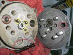
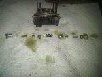
Then I would suspect the pump assy. RRitt's kits are proven to work. I don't know about the pressure, however, below is a picture of the pump assy. taken apart.

Yours may not be exactly the same, however, the differences are usually minor. There are 4 steel balls. Three circled in yellow and one in red. The spring circled in red applies pressure to the steel ball circled in red. The spring is inserted into the cavity circled in red. This is the spring that is adjusted for pressure. There are several methods. Some use shims, some use a threaded rod with a lock nut etc. The idea is to compress the spring to generate more pressure. When reassembling, use some grease to hold the steel balls in place. The smallest steel ball is the hardest to hold in place as it doesn't have much of a hole to keep it steady. The two steel balls that are the same size circled in yellow do not have a spring applying any pressure to them. They float in the channel. The small steel ball matches up with the spring that is still in place in the opposite side of the pump body. You can just see the end of it peaking out of it's hole.

Valve body1.jpg
 

Jiggz

Captain
Joined
Oct 23, 2009
Messages
3,909
Re: Force 125 tilt/trim pump bypass valve

Really very sorry to hear RRitt going away. He has been a tremendous contributor to this forum especially in the realm of Tilt and Trim. May he rest in peace.
 

Jiggz

Captain
Joined
Oct 23, 2009
Messages
3,909
Re: Force 125 tilt/trim pump bypass valve

The following is a test procedure to determine which component is causing the leak down. You will need a 3/16” brass cap and also a 3/16” plug. Both are available at Ace Hardware or some auto stores.
Step 1: Test the tilt cylinder for leak down
1. Raise the tilt cylinder fully and then support the motor with a suitable block
2. Relieve pressure by slightly tilting down
3. Disconnect “raise” line from pump assembly connecting to the bottom of tilt cylinder
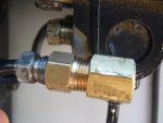
4. Cap line with the female brass cap and also the valve body port ( See Pic 1 - I didn't have the right size cap so I have to use an adapter)
5. Remove block support from gearcase
6. Mark across the swivel and stern bracket with a marker to note movement. This may take a few minutes to about 30 minutes to see movement or leak down
7. If leak down is noted, replace tilt cylinder or in your case rebuild it.
8. IF NO LEAK DOWN IS NOTED RECONNECT LINE AND PROCEED TO NEXT PROCESS
Step 2: Valve Body leak down test
1. Lower the outboard motor to full trimmed down position
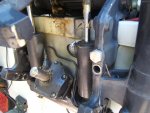
2. Remove the “lower” trim cylinder line from the valve body. This line is the one located on the upper portion of the trim cylinder (see pic 2). Plug and cap both the line and the valve body port.
3. Raise the motor to fully up position (Full tilt)
4. Mark across the swivel and stern bracket with a marker to note movement
5. If leak down occurs, troubleshoot the valve body
6. If leak down DOES NOT OCCUR, REBUILD OR REPLACE TRIM CYLINDER. NOTE THIS IS WITH THE CONCLUSION THAT THE TILT CYLINDER PASSED THE LEAK DOWN TEST IN STEP 1.
Valve Body troubleshooting:
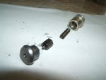
1. You do not even need to dismount the motor just the valve body. Do not disassemble the entire valve body,stead you just need to dismount the spool valve (see pic 3 although the O rings have already been removed). See first picture provided by PNW. That is one spool valve unit and your system has two of them. If you can provide pics of your spool valves removed showing all the O-rings associated with it, we can do a diagnose on what needs to be done to fix it.

Hope this helps.

DSCF1370.jpg DSCF1371.jpg DSCF1410.jpg
 

dancewithme951

Petty Officer 3rd Class
Joined
Jan 27, 2014
Messages
75
Re: Force 125 tilt/trim pump bypass valve

Thank you pnwboat and Jiggz for such detail. pnwboat, I very much doubt I'll have the cajones to take the pump apart. It looks like a land mine that might explode in my face! And frankly it looks to be completely unserviceable. I hear what you've said about there possibly being inside of mine some adjustment mechanism to increase the tension on the long spring. But knowing how difficult it is just to remove, disassemble, reassemble, then reattach the pump every time I make an adjustment sounds like a process with a very low risk/benefit ratio.

But here's what I do plan to do pump-wise. I still have the original Prestolite pump and I've never really proven it was defective. So I've ordered a set of parallel hydraulic lines/fittings and plan to remove all the 4 hydraulic lines from my currently installed pump and attach them to the Prestolite. I was bale to get that motor working before so I'll do so again and see what happens. If my some stroke of luck the Prestolite works, I'll just swap out and problem should be solved.

But, Jiggz, before I do any of that I'll first go again through the diagnostic scheme you laid out for me. And as a reminder - this has been a very long thread - I had the entire shuttle assembly apart when I first received the new pump (inadvertently). I examined all the parts at that time, ensured all o-rings were in place, and reassembled correctly. And the trim cylinder works perfectly. But if I'm able to remove all the components from the anterior of the pump body (the posterior being the transom side) I will if the diagnostic proves to be negative.

I'll send an update when I have one.
 

Jiggz

Captain
Joined
Oct 23, 2009
Messages
3,909
Re: Force 125 tilt/trim pump bypass valve

I think you have a great plan. And I totally agree as soon as you get the old Prestolite pump assy, do the test I laid out for you. It will definitely make troubleshooting easier knowing which component actually works and which one doesn't. Don't worry about the length of the thread, I've seen ones with more than 4 pages before. In fact, if you wanted to, you can go ahead and disassemble the spool valves on the prestolite valve body before re-using it just to make sure at least the hex check valve O rings are still good to go (worn out hex o-rings are 99% cause of valve body leak down in these systems). They are really easy to remove when the whole assy is dismounted. Some style spool valves are threaded in while others use C-clips to hold them in place. Look at the pic 1 above showing the c-clip in the background which is the one I got. Take pics of both spool valves post it and we can do a diagnose online.

One more thing, note that pic posted showing the disassembled valve body showing the ball check valves and springs? You don't have to do that when repairing the spool valves. In fact, most people after dismounting the valve body (held in place with four screws to the motor pump assy) they go through disassembly as shown in that pic and then struggles to put it back together. BUT YOU DO NOT NEED TO DO THIS IF YOU ONLY WANT TO REPAIR THE SPOOL VALVES!
 
Last edited:

dancewithme951

Petty Officer 3rd Class
Joined
Jan 27, 2014
Messages
75
Re: Force 125 tilt/trim pump bypass valve

OK Jiggz, set about to remove the spool/shuttle valves on the Prestolite but once the C clips were removed the piston end caps would not budge. I expected them to simply release from spring tension but neither side would move. Tried compressing in a vise with a socket but it sems to be completely frozen. I have it sitting now with some penetrating fluid but geez I don't get it. The valve body is aluminum, the end cap is aluminum so what kind of corrosion could have caused this? Any ideas?
 

pnwboat

Rear Admiral
Joined
Oct 8, 2007
Messages
4,251
Re: Force 125 tilt/trim pump bypass valve

Are you referring to the aluminum caps with the "O" rings on the left and right side of the picture below

trim tilt.jpg

I have a compressor so I just blow them out with a shot of air. I have been successful in getting them out by taking the valve body and tapping it against a piece of wood. Position the valve body so that the valve is pointing in the general direction that you're moving the valve body. The inertia and sudden stop of the valve body against a piece of wood will make the cap move slightly. Once the cap gets past the ring of corrosion, it comes out fairly easy.
 

dancewithme951

Petty Officer 3rd Class
Joined
Jan 27, 2014
Messages
75
Re: Force 125 tilt/trim pump bypass valve

Well I did a lot more than tap it and it did not budge. Maybe after the Liquid Wrench...later.

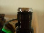
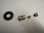
Hope you're still online Jiggz or Pnwboat. I went ahead and removed the anterior shuttle valve from the Chinese pump now on the boat. This is the end that I was talking in my first post that fell apart in pieces. I put it back together as it should be but I have a question. The aluminum cap with the o ring that slides into the black endpiece with the hex head that is seen from the outside of the pump (mine does not use c rings)..how flush in that black piece should it sit. It was pretty tight when I assembled it and I never got the o ring to touch the shoulder of the black piece. Does that matter? Here's a picture so you can see the gap.P1010555.jpg
 
Last edited:

pnwboat

Rear Admiral
Joined
Oct 8, 2007
Messages
4,251
Re: Force 125 tilt/trim pump bypass valve

Liquid wrench, PB Blaster, a small amount of heat etc., eventually you'll get it.

If you do get access to an air compressor, make sure you put the retainer ring in on one cap so that they both don't go flying across the room in opposite directions. Don't ask me how I know. LOL!
 

Jiggz

Captain
Joined
Oct 23, 2009
Messages
3,909
Re: Force 125 tilt/trim pump bypass valve

I wish you had provided a picture of the part(s) you are referring to. But if what you are referring to is the removal of the spool valves themselves (held in place by C clips in your case as you mentioned) the best way is to use air pressure with a narrow air blow gun. Blow a short blast of high pressure air into one of the holes located on the top side of the valve body (this is where oil goes to when the pump is running) and this will force the spool valves out of the VB. Just make sure one clip on the other side is still in place to prevent both from flying away. Use a rag to catch spool valve and the shuttle valve. As for the other side, no air is required, just push it out with a wood or plastic rod from the now opened other end. Tap if you need to but it will bulge. The pic provided by PNW is perfect illustration on the arrangement of the two spool valves and one shuttle valves (the one that moves left or right to direct the flow of oil into the ports).

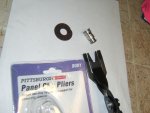
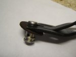
As for the disassemble of the spool valves itself, you need to be careful not to dent or gouge its sides. There are two ways to do this, use high air pressure into the little hole on its body forcing the cap out (again use rags to catch the cap, spring and the hex check valve). Or you can use an upholstery or panel clip pliers as shown in the pic below. I used the 1/2 flat washer (hammerred a little to make the hole off round a little) to provide shoulder for the pliers to push against the spool valve body while prying out the its cap. The pliers is available at HF for less than $10.

DSCF1403.jpgDSCF1407.jpgDSCF1408.jpg
 
Last edited:

pnwboat

Rear Admiral
Joined
Oct 8, 2007
Messages
4,251
Re: Force 125 tilt/trim pump bypass valve

Hmmmmm......I see the gap between the "O" ring and the groove. That's the end of the plug that rests against the shuttle valve isn't it. Is the shinny aluminum plug with the small hole inserted all the way in? I think as long as the "O" ring is tightly sealed on the inner and out circumference, you should be OK.
 

dancewithme951

Petty Officer 3rd Class
Joined
Jan 27, 2014
Messages
75
Re: Force 125 tilt/trim pump bypass valve

Thanks pnwboat. Jiggz, and comment from you as to whether that gap is ok? In other words, per your third picture above, should the part on the far right with its o ring in place fit snugly into the piece on the far left? You can see in my picture there's a gap...it won't go in any further without great persuasion. Could that be part/all of my problem?
 
Top