Closed Cooling System on Port Engine Running Hot(ter)

achris

More fish than mountain goat
Joined
May 19, 2004
Messages
27,468
No Title

tpenfield

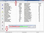
This is the file from the port engine.
 

Attachments

  • photo249404.jpg
    photo249404.jpg
    184.4 KB · Views: 0

NHGuy

Captain
Joined
May 21, 2009
Messages
3,631
Throwing out some ideas for you. This is complete conjecture, but with a dash of maybe.

Do you have a bore scope? If so have a look in the combustion chambers after you do the compression test. And especially in any holes that are different from the norm.

Is your fuel injection a rail style? Rails can be removed and cleared. Injectors can be inspected and/or swapped. You might get a set of injector o rings before doing that. I did that with a Ford truck, the rings cost pennies. If you do that clean or blow off the tops of the injectors before removal so no crap goes in their holes.
What is up with your motor, guy? Gotta be something!
 
Last edited:

tpenfield

Moderator
Staff member
Joined
Jul 18, 2011
Messages
17,869
Chris - Got it, thanks.

NHGuy - I do have a borescope that I plan on inspecting the exhaust valves with. The engine has what looks like to be a single fuel rail that runs down the center of the manifold. VST fuel system. Just for kicks, I ran a 50/50 mix of fuel and injector cleaner through the system last weekend.

Next steps along those lines would be to do the pressure test on the fuel rail.
 

tpenfield

Moderator
Staff member
Joined
Jul 18, 2011
Messages
17,869
I swapped the controller units (MEFI) and ran the engines up to temperature. The overheating condition stayed with the port engine, The connectivity problem also stayed with the port engine , so I still could not run any tests on the port engine after switching the controller units.

Also the starboard engine still thinks it's in charge as it comes up as the master and the port engine still comes up as the slave.

I can run all the test on the starboard engine but none of the tests on the port engine. It still comes up with the no reply error message that it was getting before on all the tests.
 
Last edited:

tpenfield

Moderator
Staff member
Joined
Jul 18, 2011
Messages
17,869
Real-time update:

I did the fuel rail pressure check. There is a male Schrader valve on the rail so that was convenient.

Port - 34 psi initial dropped to 30 psi after about 2 seconds

Starboard - 40 psi initial dropped to 34 psi after about 2 seconds

So, I think I have found the problem - Port engine fuel pressure is too low, I believe it's supposed to be between 37 and 43 PSI, but I am not sure if that's the initial reading for the reading it drops down to after a few seconds.

Now it looks like I need to investigate the VST fuel system pressure pump. Not sure if there is a way to adjust it or if I have to break out another thousand :rolleyes:
 

HT32BSX115

Supreme Mariner
Joined
Dec 8, 2005
Messages
10,083
Last year I noticed the port engine started to run a bit higher than it did previously (165-170) and took noticeably longer to 'recover' when going from cruising speed down to wake speed.

Ted. I went back to the beginning to look for where you had swapped the temp gages to verify them and started thinking about a problem I had with a Ford Taurus a few years back.

My Mo-in-law complained that her heater wasn't making warm air so I started looking for obstructions in the cooling system (particularly in the heater core)

Now aside from maybe just trying to make it worse :eek:(I actually have a pretty good relationship with her so I shelved that idea!!;);))........ The heater core was actually nearly plugged but that wasn't the whole problem!

I DID find that due to what I discovered later was electrolysis, the stamped steel water pump impeller was nearly corroded away (the impeller looked like a wimpy saw-blade!!) and simply could NOT move an adequate amount of water/AF mix through the heater core. She didn't mention what the temp gage was doing, but truth be known, she never looked at it anyway!!!

I have never heard of electrolysis happening in the cooling system of a closed cooled marine engine, but now that I think of it, I seem to remember my San Juan Engr FULL system having a "zinc" in the closed cooling side. Is it possible that this thing has disappeared and now your impeller has started to disappear as well?

Your description above that it now takes longer to "recover" at idle might indicate that the pump doesn't move enough coolant to "recover" as quickly as the STB engine, might tell me that the port recirculating pump isn't moving as much coolant as the STB engine at idle.

Also, heat transfer RATE at idle after a hard run would NOT seem to be related to fuel mixture, timing or other NON-cooling system issues. Engines at idle regardless of fuel mixture, timing etc don't generate a huge amount of heat.

So the cool down rate would seem to be directly proportional to the (recirc-pump) coolant flow rate assuming raw water flow rates and heat exchanger efficiencies are approx equal.

In that old Taurus, the coolant temp with the "saw-blade" pump didn't over heat driving down the road because it actually moved *some* coolant though the engine and radiator BUT, It DID run considerably hotter than "normal" .........AND the temp didn't drop much at all at idle. (after replacing the pump, everything went back to normal)

Just trying to excercise my 40 years back thermodynamics training and suggesting another "tree to bark-up" while looking for the right one!! Don't sell that thing yet!!

Cheers,

Rick
 

tpenfield

Moderator
Staff member
Joined
Jul 18, 2011
Messages
17,869
Thanks Rick, for the info on the cooling system. I do replace the Zinc in the H.E. on an annual basis. So I would think that the impeller is probably OK. If it weren't I would expect to see a greater temp rise in the exhaust manifold thought, which I didn't Not saying it is impossible, but for now I will chase the fuel system pressure.

I notice that there is a 'regulator' and a 'filter' which is attached to the fuel rail on the VST system . . . wondering if these have adjustments or have to be replaced. VST pumps are a bit pricey, so I hope that is not the route.
 
Last edited:

tpenfield

Moderator
Staff member
Joined
Jul 18, 2011
Messages
17,869
Another update:

I read the fuel system section of the service manual regarding testing the VST system. According to the manual, you can isolate a low pressure issue to either the pump or the regulator by blocking off the return fuel line and then checking the rail pressure. You need at least 38 psi to be good.

So, I pinched the return line and did the pressure check again. I got 48 psi, so it looks like the pump is OK and the regulator is tired. I plan on ordering 2 new regulators, as the starboard engine was borderline (34 psi) according to the testing procedure outlined in the manual.

Hopefully, this will do the trick.
 
Last edited:

HT32BSX115

Supreme Mariner
Joined
Dec 8, 2005
Messages
10,083
So, I pinched the return line and did the pressure check again. I got 48 psi, so it looks like the pump is OK and the regulator is tired. I plan on ordering 2 new regulators, as the starboard engine was borderline (34 psi) according to the testing procedure outlined in the manual.

Hopefully, this will do the trick.
Two crossed fingers!
 

achris

More fish than mountain goat
Joined
May 19, 2004
Messages
27,468
So what's the deal with the connectivity and error problem? I think that needs to be sorted too. Could be a dodgy ground somewhere.
 

tpenfield

Moderator
Staff member
Joined
Jul 18, 2011
Messages
17,869
So what's the deal with the connectivity and error problem? I think that needs to be sorted too. Could be a dodgy ground somewhere.

I am wondering if it is related to the mater/slave identity of the engines? There is not much info on the internet to go by. I could pose the question to the folks at Rinda Technologies.
 

achris

More fish than mountain goat
Joined
May 19, 2004
Messages
27,468
Bit more research for you Ted. The engines are connected to each other via a Dual Engine Data Link Cable. Now, mid 1996 Merc moved the connector wire to the Diagnositc Data Link Cable. Not sure which one you have, but it would be a great test to dicconect the cable that joins the engines and then run the Diacom tests again. Do you have Merc service manual 16? (I think that is the right one for your engines.) Have a look at section 4F (Wiring diagrams), Page 8. Look at connectors 6 and 21.

The other thing I would check is the ground cable between the engines. Make sure a) there is one, b) the connections are clean and tight. Should be a battery size cable. ;)

Chris........
 
Last edited:

tpenfield

Moderator
Staff member
Joined
Jul 18, 2011
Messages
17,869
Bit more research for you Ted. The engines are connected to each other via a Dual Engine Data Link Cable. Now, mid 1996 Merc moved the connector wire to the Diagnositc Data Link Cable. Not sure which one you have, but it would be a great test to dicconect the cable that joins the engines and then run the Diacom tests again. Do you have Merc service manual 16? (I think that is the right one for your engines.) Have a look at section 4F (Wiring diagrams), Page 8. Look at connectors 6 and 21.

The other thing I would check is the ground cable between the engines. Make sure a) there is one, b) the connections are clean and tight. Should be a battery size cable. ;)

Chris........

OK, will do. My boat was built in early January 1996 and the engines are #36 and #39 of the Gen VI serial number series, so pretty early in the production run.

It would be nice to get the Diacom stuff all sorted out. I'm hoping that the fuel system pressure is the cause of the overheating issue and that new regulators fix it.

I have new regulators on order and hopefully I can get them installed for next weekend. :)
 
Last edited:

tpenfield

Moderator
Staff member
Joined
Jul 18, 2011
Messages
17,869
I just checked the manual . . . don't remember seeing a yellow wire leading into the DLC, so I'm thinking it is the 'pre- 1996-1/2' version.

I'm assuming that I would just disconnect 'connector 21' which has 3 wires leading to it - yellow, black, orgn/blk ? Do I have to do that on both engines or just 1 engine ?
 

achris

More fish than mountain goat
Joined
May 19, 2004
Messages
27,468
I just checked the manual . . . don't remember seeing a yellow wire leading into the DLC, so I'm thinking it is the 'pre- 1996-1/2' version.

I'm assuming that I would just disconnect 'connector 21' which has 3 wires leading to it - yellow, black, orgn/blk ? Do I have to do that on both engines or just 1 engine ?

It's an 'engine to engine' link, so just one will do the job.
 

tpenfield

Moderator
Staff member
Joined
Jul 18, 2011
Messages
17,869
One question I had (for anyone listening in on this thread) Is how easy a task it will be to install the new regulator. My main concern is it being fuel related. the regulator on these engines are located on the bottom of the fuel rail at the forward part of the engine, right behind the thermostat housing.

It seems like it is held in place with 2 bolts, and the pressure of those bolts upon the o-ring/grommet on the mating surface between the fuel rail and the regulator makes for the tight seal. Is that all there is to it :noidea:

It seems like when I remove the old regulator the fuel rail will dump its contents onto the intake manifold. I am wondering if there is a procedure for changing the regulator that touches upon removal of the regulator and re-priming of the rail once the new regulator is installed :noidea:

I'll check the manual, but if someone knows more specifically, that would help. :)
 

tpenfield

Moderator
Staff member
Joined
Jul 18, 2011
Messages
17,869
Well, it looks like the manual prescribes removing the fuel rail in order to replace the regulator. There is just something that worries me about taking apart a 20 year old fuel system :rolleyes:

I might try to replace it with the fuel rail intact.
 
Top