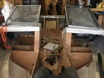
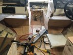
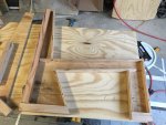
Capri 1950 Resto and Modernization

Capriupgrade

Seaman Apprentice
Joined
Jan 24, 2019
Messages
33
Hi All!

Long time lurker, first time posting. I am excited to try and add some entertaining content to the already amazing amount on iBoats!

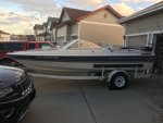
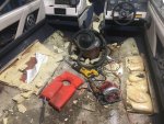
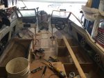
So, back in December I got a wild-haired idea that I wanted to get a boat for my GF (now fiance). One thing led to another and I ended up finding a good score on a 1996 Bayliner Capri 1950 with a rotten deck and low hours 3.0 mercruiser. I took a gamble on this boat as the owner's dad was a mechanic and "appeared" to care for the motor, so worst case I could scrap the boat if it turned out to be too rotten and recoup my investment by selling the motor.
Well...after doing some preliminary dissecting, I determined that this old bayliner was worth saving and is destined to be modernized! (I came to this conclusion after reading a bunch of amazing restorations on iBoat. So, I entirely blame iboats for putting me onto this crazy idea of a boat project! lol). Fast forward 8 months, after doing most of the deconstructing and deck installation, my Fiance suggested we should blog this project. So here we are!
But, before I get everyone caught up on the current state of this project, let me give some background.

About me - I am a native Coloradoan, somewhat new to the boating scene because, you know, Colorado has essentially only ponds. My day job keeps me thoroughly bored peddling paperwork in the pharma industry. When not at work, I have a small fabrication shop (Machning/CNC, welding, wood, etc) crammed in my garage that keeps me busy on occasional contract jobs, but more likely working on the endless list of stuff to fix. Fiberglass is new to me/us, so this is an exciting opportunity to learn a new skill.

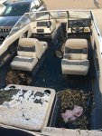
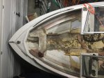
About the Boat - It is a 96' Bayliner 1950. It was a fishing boat in Arizona for most of its life and then came out to Colorado around ~2010. It was then parked in this guys yard in 2011 and didn't move/run since. The hull is in good shape, only a few small nicks down to glass on the keel that I will have to repair. The deck was obviously rotten as the ski locker was completely collapsed. Motor looked clean and was properly winterized in 2011, so I took the risk.

The Vision - Going into this, I knew the deck was going to be replaced, which would give me a blank palette to customize to my heart's desire (but within time and monetary limitations or course.). So, first thing first, the back to back mid-ship seats and those cheesy jump seats on either side of the engine cowling must go, cause they are uuuuuuugly. Instead, the back 2-3 feet of the boat will get a 3-peice sun platform over the engine, with gull-wing style hatches on either side of the engine for cooler storage. Next comes a full length 3-person bench in front of the engine, which then makes an "L" down the passenger side. The passenger gets a flip down back to make a lounging area (Just like the newer Bayliners in Tiges). The driver seat will be its own box, with space for a table or cooler between the back bench and it. The driver backrest will also flip forward to allow the driver to face aft while anchored. The bow area will stay the same, but will get some more cup holder options around it. Every square inch will then get gel coated bright white and then EVA foam flooring installed. All seats will get a custom upholstery job with a color theme of off-white, brown, navy blue, and tan, in that order of appearance. A wakeboard tower then tops it all off and I just hope the 3.0 has enough sack to get a board out of the water! lol.

Now, to the first few pictures! (Since this is my first post, I apologize if any of these photos get screwed up). Also, It will probably take a few days to get caught up, because I am pretty far into this already.
 

Attachments

  • photo318881.jpg
    photo318881.jpg
    52.7 KB · Views: 13
  • photo318882.jpg
    photo318882.jpg
    2.3 MB · Views: 10
  • photo318883.jpg
    photo318883.jpg
    2.1 MB · Views: 12
  • photo318884.jpg
    photo318884.jpg
    2.1 MB · Views: 9
  • photo318885.jpg
    photo318885.jpg
    1.8 MB · Views: 9

dezmond

Senior Chief Petty Officer
Joined
Jul 21, 2010
Messages
760
Welcome aboard! Looks to be a lot of fun and work. Remember to check your stringers and transom for any rot. I have the mini me of what you have and have been working on mine since last summer. It’s a lot of fun. Make sure you get proper masks and suits when you do your grinding. I am converting mine to a center co sole just because. If I can help in any way just ask. Good luck and will be following along!
 

Capriupgrade

Seaman Apprentice
Joined
Jan 24, 2019
Messages
33
Thanks dezmond! I stumbled on your build a few days ago and have been trying to catch up on it. I am only 1/4 through it, but looks great so far! Definitely some good tips in there...

I hear you on the PPE! I started in on it with just a cheap respirator with some 3M P100's, but then upgraded to a full face and will never go back! It is awesome and is way more comfortable than the respirator, IMO. Thanks for the heads up though! No sense ruining a perfectly good set of lungs with fiberglass...
 

Capriupgrade

Seaman Apprentice
Joined
Jan 24, 2019
Messages
33
Alright, Story continued, now that I have figured out how to post photos inside the the post -

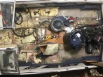
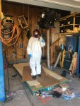
When I got it home and in the garage, the exploratory surgery began. (with help from the Admiral of this yet to be commissioned vessel.)
Click image for larger version  Name:	IMG_6184.JPG Views:	1 Size:	1.75 MB ID:	10787912Click image for larger version  Name:	IMG_6201.JPG Views:	1 Size:	1.74 MB ID:	10787911
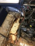
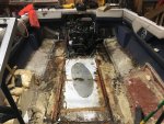
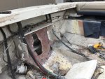
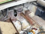
As you can see. Very rotten. The port side is just mush and the only thing holding it together is the fiberglass. We keep on plugging away, trying to see how bad it is.
Click image for larger versionName:	IMG_6204.JPGViews:	1Size:	1.85 MBID:	10787913
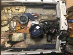
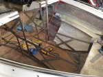
We cut out the seat boxes and were surprised to find so much foam! Bayliner sure was creative in finding places places for foam. But, it has to go - I want a nice and flat deck to work with. I figure I removed about 2 cubic feet per side that I will have to figure out how to move somewhere else. I am thinking maybe pool noodles under to gunwales in the cap? Terrible Idea?
IMG_6209.JPG
Got it the deck out! the portion over the tank and under the seat boxes was determined to stay in the boat! But it stood no chance to my trusty oscillating cutter.

More surgery...
IMG_6501.JPGIMG_6498 2.JPG
Because those boxes under the consoles were built on the deck, I decided the had to go too. And guess what? More foam! lol. This foam will be largely replaced though in some sort of similar arrangement.

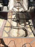
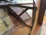
After getting everything cleaned out, it was time for some biopsies to assess the level of cancer throughout the boat. Fortunately, I found the stringers properly encased all the way to the rear bulkhead, which I think largely saved the wood inside. 1/4" drill bit every foot or so along the stringers found nothing but good wood. Yippee!

But that is where the good news ended. I think the front half of this boat was built by a seasoned vet, whereas the back half was built by a greenhorn. For whatever reason, aft of the rear bulkhead, the rear stingers were not encased at all. They only had a fiberglass skin on the bilge side and nothing on the foam side. So, no surprise, the back foot of the port stinger was mush. The starboard stringer had some surface mold that was easily sanded off with solid wood beneath. whew.

So at this point, it was time to step back from the hull and look at the motor to see if it was worth continuing on.
 

Attachments

  • IMG_6184.JPG
    IMG_6184.JPG
    1.7 MB · Views: 7
  • IMG_6499 2.JPG
    IMG_6499 2.JPG
    1.9 MB · Views: 8
Last edited:

Capriupgrade

Seaman Apprentice
Joined
Jan 24, 2019
Messages
33
Before I invest a ton of time and money into this boat, I want to make sure the motor runs. Time to find all the plugs and de-winterize it from its 8 year slumber! Since I had removed the outdrive to fit it in my garage, this presented a cooling predicament. I am always fixing cars I have a collection of Tees from those prestone coolant flush kits. Well, one of those Tees just happened to fit the water supply line for this engine. So I spliced it in just upstream of what I assume is the thermostat housing. Pinch off the supply line at the drive inlet and wala! Water cooling, sans outdrive.

I replaced the spark plugs, charged a battery, and tried it out. It turn over! Step one - check. Next was to get it some good gas as I assumed the gas was bad being 8+ years old. So I just put the gas line into a 1 gallon can of fresh gas. Then tried to fire it up. Crank Crank Crank Crank Crank, nothing. Repeat, nothing. this is when I notice it is turning over really hard. So, I put a wrench on the crank and give it a manual turn. It turns, but it had a surprising amount of resistance. At this point, I am like, "Crap, one of the pistons is binding". I pull all 4 spark plugs and give it a crank. Spins with almost no resistance whatsoever. Awesome. It just has such good compression it was making me worried something was wrong.
But why wont it start? Ah, not getting fuel in the carb. Must be some sort of head pressure issue with the fuel line going up and then down into a fuel can. Now, I know the old fuel has to be bad because its 8+ years old, but I smelled it and it smelled fine. What the heck , try it out!. What do you know, it fires right up! I guess they put Stabil in the fuel or something?


I ran it for probably 20 minutes. It idled fine and accelerated okay, in the little burst that I did. I was scared to open the throttle too much for fear of not having enough cooling water. The engine got warm, but never hot.

Mission successful! Engine runs and is workable. I will worry about tuning it up when the boat is done. This was back in January/February, so I had to re-winterize the block. Hopefully I did it right! :nonchalance:
 
Last edited:

dezmond

Senior Chief Petty Officer
Joined
Jul 21, 2010
Messages
760
GOod to hear the engine runs. After the year out and clean is done, you will
be much more excited seeing it go back together. Trust me on that one. You will get “gotta grind more” a lot but do as your told
from these guys. When I got my new decl
put back in I was smiling from ear to ear. Then you have your blank canvas to work with Ask lots of questions if in doubt. Everyone on here has a great wealth of knowledge. Even if they do bash our Bayliner ;). Have fun!
 

TwoBallScrewBall

Lieutenant Commander
Joined
Sep 14, 2003
Messages
1,695
Looking forward to watching this one, that was my first boat (mine was an 88), same motor and all. Hoping I can help you out along the way!!!! Welcome :)
 

Capriupgrade

Seaman Apprentice
Joined
Jan 24, 2019
Messages
33
Thanks TwoBallScrewBall! Oh really? What did you think of the motor performance? The admiral is slightly concerned with its ability to tow a wakeboarder. I think it will do just fine as I have read it has a great hole shot, just not the high top end speeds that we don't need for wakeboarding anyways.

Yeah, no kidding dezmond! It was really hard to motivate myself to go get itchy during the winter and spring months... Cut cut cut. Grind grind grind. No fun! But now that I am getting into the reconstructing phase, it is very exciting to see things starting to come together. (I am still working on getting everyone caught up to present).

Ha! See, I think the naysayers have it wrong. Bayliners are 80% exceptionally well made and 20% "WTH did they do here?!". But if you take the positives and subtract the negatives, you still have a 50-60% exceptional well built boat. :D
 

Capriupgrade

Seaman Apprentice
Joined
Jan 24, 2019
Messages
33
The story continues!

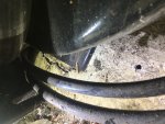
Fast forward a few months to early spring, I was poking around the motor looking at what was needed to pull it out so that I could work on the port stringer. To my dismay I noticed this little bugger of a crack in the transom just below the drive...
Click image for larger version  Name:	IMG_6936.JPG Views:	1 Size:	2.17 MB ID:	10788267
I had previously assumed that that transom rot was caused by lake water seeping in from the exterior. The drive felt solid when I bought it and since it was a trailer queen, I assumed the transom was golden. That's what I get for assuming...
Click image for larger version  Name:	IMG_6933.JPG Views:	1 Size:	1.82 MB ID:	10788268
Drilled a few hole. Yup, very very rotten. :sorrow:
But, no time to wallow in my sorrows. Time for the motor to come out! (plus, I am sure you all are like, "Could have told you it was going to be rotten"). I guess that's why Dezmod calls his project the Dirty Rotten Bastard!
Click image for larger version  Name:	IMG_7314.JPG Views:	1 Size:	2.13 MB ID:	10788269

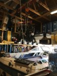
And it's out! Man, I wish all motors came out this easy! I spent more time setting up the rigging than actually removing the motor.
Click image for larger version  Name:	IMG_7313.JPG Views:	1 Size:	1.65 MB ID:	10788270
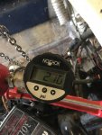
I wanted to know how much this motor weighed - this is my homemade 5,000# lifting scale. the gauge has 90 PSI pre-load (not sure why) and requires a 2.3 multiplier to go from PSI to pounds (surface area of hydraulic piston). This gives a weigh of ~415 Pounds, in case anyone is curious.
Click image for larger version  Name:	IMG_7318.JPG Views:	1 Size:	1.50 MB ID:	10788271
And the drive is out!
Here is a trick I learned about removing fresh oil from concrete - spray it down with WD40, wait 10 minutes, and then hose it down. After a day or so, the stain fades completely away. Wanna know how I know this? Well...I put the transom portion of the drive into a storage bin so that I could contain any leaking oil from the remote oil container. At some point in the night, gremlins knocked the bin over, spilling ~1/2 qt of oil all over the garage floor. To add insult to injury, the trash can I put the oil-soaked rags in had a hole in it, so I dripped oil all the way across my driveway and down the sidewalk to my trashcan.
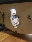
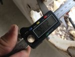
Click image for larger version  Name:	IMG_0549.JPG Views:	1 Size:	1.51 MB ID:	10788272Click image for larger version  Name:	IMG_1146.JPG Views:	1 Size:	1.49 MB ID:	10788273
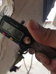
Before I tore out the rot, I took some reference measurements. Looks to be as specified by mercruiser. 2 - 2.25". Variability was within 1/16 around the hole.
Click image for larger version  Name:	IMG_2007.JPG Views:	1 Size:	2.02 MB ID:	10788274
As dezmond says it, Dirty. Rotten. Bastard.
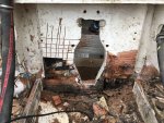
Careful forensic analysis determined that, because the bastards at Bayliner did not encapsulate the stringer and did not isolate the transom from the stringer with tabbing, the port side stringer cancer was able to metastasize into the transom. Fortunately the rot did not make it into the starboard stringer, somehow. I think the crack mentioned before was from hydraulic fracturing when the infiltrated water froze in the transom.
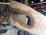
Despite the rot, the transom was very difficult to remove. I was trying to be gentle at first and pull the whole thing out as a template. But then it fought me, so I fought back with a circular saw, demo hammer, and finally I had to fight dirty with my 14" carving chainsaw (Not pictured, too graphic).
Click image for larger version  Name:	IMG_7416.JPG Views:	1 Size:	1.88 MB ID:	10788275
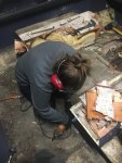
The admiral is gearing up for some heavy duty sanding! This is our medium weight battle gear. If things get really hairy, we upgrade to the PAPR (Powered Air Personal Purifier). These are nice as they are like a mini-AC in your suit. Downside is it inflates your suit and makes you feel like the Michelin man, which is difficult to maneuver in. So far, the full face respirator has been all we need, and has been awesome.
Click image for larger version  Name:	IMG_7414.JPG Views:	1 Size:	2.01 MB ID:	10788276
First pass sanding done. I got to tell you, I know everyone swears by a grinder for rapid material removal, but this dewalt variable speed sander I have takes the material off just as well, has a vacuum shroud, uses standard 5" disks, and is much quieter. The only downside is it can't get into corners as well because of the shroud, and you have to watch sharp things (like staples), as they will tear you disks. I highly recommend this tool!
Now, while I am sure this is controversial, I have decided I am going to leave the shelve above the ransom. I have a few reasons for this - For one, I want it there, which means I will have to reinstall it if I cut it out. Second of all, it is already tabbed into the hull. Third of all, when I tab the new transom into this shelve, the truss action of this perpendicular member will add bundles to the structural integrity of the transom. Anyone see a problem with this? I have not installed the new transom yet, so there is still time to change.
 

Capriupgrade

Seaman Apprentice
Joined
Jan 24, 2019
Messages
33
Alright - lets talk about that rotten stringer.

So, I started poking around on it and found that there was about 1' of good wood poking out from the aft bulkhead. Many may disagree with this approach, but in my mind, 1' is plenty to scab on a sister stringer in place of the rotten portion. This is a very common practice in other industries, why not here? In this case, I have a 2' replacement portion, and 3' of new "sister" stringer. Should be plenty strong.
IMG_7437.JPG
Unfortunately I only took this one photo during this repair. But here are the details - I bonded the replacement stringer to the sister stringer with one layer of 1.5 oz CSM. I then mixed up a big batch of hairy PB and spread it everywhere, including between the old bilge fiberglass skin and the new stringer. A piece of 4" channel iron and lots of clamps held everything in place until it cured. The new stringer and sister were bedded to the hull with ~1/4" of hairy PB.
Not pictured - I then ground out all the bilge and tabbed and encapsulated both port and starboard stringers with CSM. Considering Bayliner didn't even bother encapsulating these stringers before, this time they should last at least another 25 years. Plus, there is now a layer of CSM between the stringers and the yet to be installed transom, if one rots, it wont take out any others.
 

kcassells

Fleet Admiral
Joined
Oct 16, 2012
Messages
8,718
I woulda ripped out and reinstalled all new. JMHO. Cause that is the way to do it. Your boat do what you want. :eek:
 

chevymaher

Commander
Joined
Mar 29, 2017
Messages
2,921
LOL I am with kcassells. I said if I found anything when I started it was all coming out. The 2 outer stringers were perfect. Ripped them out anyway on principle. It is all gonna be new. Past tense of thinking. it is finished now.
 

Capriupgrade

Seaman Apprentice
Joined
Jan 24, 2019
Messages
33
Thank you for the feedback guys. I am fully expecting most people to disagree with me on not replacing the whole stringer, so no surprise here, nor any animus towards you guys. I am a big advocate of the "do it right or don't do it all" mentality, but in this case, what is truly required for a 99% worry free build? Because, when looking ahead at the enormity of a boat restoration, I feel that selectivity based on calculated necessity is your best friend. Selectivity based on "principle" is a dangerous rabbit hole. Just my 2 cents though...
Of course, I see the counter argument - "considering the amount of work you are going to put into this thing, you need to make sure the bones are solid, otherwise the rest is worthless"

So, let's have a thought exercise about the "bones" of a fiberglass boat.

On this boat, the stringer is a ~12 foot piece of 3/4" plywood, approximately 6" tall. From a structural perspective, for this span, this beam is nearly worthless. Let's look at this with a distributed load of 2000 pounds, or 167 lb/ft (potentially worst case - all boat's weight on one stringer).

167 pounds.jpeg
167 pounds defelction.jpeg
With these values, this gives an upward deflection of 4.7". Almost worthless as a structural member in the vertical (Beam) plane.
Okay, now lets assume the maximum permissible deflection for the stringer is 1". What is the maximum distributed load for this deflection?
35 pound.jpeg35 pounds defelction.jpeg
35.5 lbs/ft. Or 426 pounds of distributed weight. Again, nearly worthless as a beam for this application as 400 pounds is two people. A fully loaded 19' boat could weight close to 4000 pounds, which I am now realizing makes the first deflection nearly doubled for worst case (all weight on one stringer).

So, if these numbers are to be believed, what really is the primary purpose of the stringer? I think, and correctly me if I am wrong, that the stringer's prime role is to support the deck and to provide a tensile element bonding the deck to the hull. Let me illustrate my thought process with some crude drawings:
hull def no deck.jpeg
If we simplify the hull as a Vee, the forces acting on it it are going to try to push the walls inward (red is the deflected state). This is because the keel, as a compound curve, is so rigid that it will not deflect hardly any. Same with the top, with its compound gunwale. The stringers, on the other hand, will provide very little resistance to the hull moving in the inward direction. The only protection they provide is to a point load, but if that point load not directly on a stringer, it's not going to help much anyways.

Now let us visualize only a deck and no stringers:
hull def only deck.jpeg
In this case, the hull will deflect inwards and the deck will deflect either upwards or inwards. No good. Conversely, this also means that a person standing on the deck will deflect the deck downwards and pull the hull inwards. Also no good.

So what do we do? We add stringers to keep the deck-to-hull relationship fixed. Essentially making a truss if you will.
hull def deck and stringer.jpeg
Now, any inward deflection of the hull is resisted by the stringers holding the deck to the hull. This means, drum roll please, that the stringers are not important for hull compression, but rather tensile forces between the hull and deck. (Which can really be provided by the fiberglass encapsulation). Perhaps this is why some manufactures have gone to hollow fiberglass stringers?

I am by no means a hull expert. But I feel like my assumptions and logic above are pretty reasonable. Or at the very least, I had fun with this thought exercise to distract me from the work document I am supposed to be writing right now, lol.
 

chevymaher

Commander
Joined
Mar 29, 2017
Messages
2,921
Wood wicks water. The far end is just as wet as the rotted part. Only question is the bacteria in it down there. If it is it is gone. If not. it is just to wet.

I had stringers that were wasted in one area. Good for a long stretch then rotted again. Honestly water don't seem to be the key to rot. It is a place where air can get to the wood. All rot radiates from the spot where air can reach the wood.

People have done the patching before. They don't come back in a few years or check it again.

Anyway as long as you know it is your choice.
 

Capriupgrade

Seaman Apprentice
Joined
Jan 24, 2019
Messages
33
kcassells and chevymaher - Yeah, you are both probably right...It would have ultimately only cost me a few weeks of work. But the deed is done and I am now on a tight timeline to get my garage free, so going back isn't really an option.

To give myself some piece of mind, are there any external warning signs I can look for to indicate a potential issue associated with a bad stringer? Not that I expect it to be an issue, but just to be cautious.
 

Capriupgrade

Seaman Apprentice
Joined
Jan 24, 2019
Messages
33
Now, let us talk about the deck. When I removed the old deck, I kept a few feet of it from above the gas tank for later forensic analysis.
IMG_7790.JPGIMG_7789.JPG
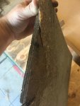
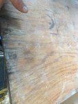
The plywood they used definitely was not marine grade as it there were voids throughout. They probably used APX or something similar at 1/2" thick. On the bottom side, they did a resin coat and on the top side they put a layer of CSM on it. The CSM might be 1.5 oz, but it sure looks a lot thinner.
Because the name of the game for boats is "weight, and how to keep it down", I intend to follow the original construction methods, for the most parts.

So, for the deck, I used exterior grade 1/2" plywood just like bayliner used. For cutting templates, I have seen a few different methods on iBoats - generally cardboard or pink foam cut to fit. I have a slightly different method, which I use anytime I need to match a strange contour. I will find any type of thin and long material - generally old lath, thin strips of cut cardboard, or drywall shim stock (prefered). As you can see below, I get out the trusty hot glue gun and start cutting and gluing the strips together and to the boat, until I have an accurate perimeter, then I reinforce it so that I can pull it out without it distorting.
IMG_7424.JPG
I like this method a lot as I don't have to trial and error cut the cardboard and I can see through and all around the template. Also, if I need some sort of bevel, I just glue a little strip perpendicular to the template at the angle it needs to be. Try it, you wont be disappointed. I pretty much get a near perfect fit 95% of the time on the first try.

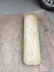
After I cut out the deck pieces, I decided I wanted to glass in a ski locker hatch flange. I had the original aluminum flange, but I figured the glass and gel-coated flange would look really nice, add a lot of rigidity to this portion of the deck, and would give me practice glassing complex shapes outside of the boat. Unfortunately I took very few photos and the deck is installed, so it may be hard to visualize what I did. But here goes it -
IMG_7427.JPG
After I cut the hole, I used the router to put a radius on both sides of the hole and then wrapped CSM around the edge. The intent here is to give a semi-finished glass inner edge so that I don't have to do any layup on the inside edge after the flange is molded. Don't worry, both sides will get resin coated and then a layer of CSM to blend all this together.
IMG_7436.JPG
I then made a plug from the piece I cut out of the deck - I cut it down to give a 1/8" clearance on all sides from the newly glassed in hole. I then cut a second piece 5/8" smaller on all sides and screwed it to the first piece. This will create a 1/2" downward "lip" of the flange. I filled any voids and caulked the corner between the pieces to give a nice radius. Then they got 4 coats of PVA. I then put this into the deck hole and screwed the hole assembly, bottom side up, down to a handful of really straight 2x4's (to eliminate any twist or curve in the deck while laying up CSM).
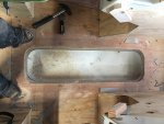
I was concerned about strength of this portion because this part of the original deck had completely collapsed. So I cut some 4" wide strips of 1/2" and laminated them around the perimeter of the hole, spaced 3/4" away from the edge. See below for a picture I tried to take from the bottom side.
FullSizeRender.jpg
It's hard to tell, but this is from below the deck and you are looking at the corner where two of the 4" strips meet. All of the strips got a healthy radius to easy layup.
IMG_7779.JPG
And here is the finished product. For my first complicated layup, I thought it turned out really well. It is super strong now too. It doesn't deflect any with 200lbs of my fat butt standing on one foot on one side of the edge.

The photo above is out of order, but after I got the flange molded, I proceeded to grind out the hull around the perimeter of where the deck will be tabbed, and areas that may be difficult to grind after the deck is installed. I choose to delay my serious grinding until after I had the interior framed in because I didn't want to waste time grinding areas that might get boxed in and foamed. I fully admit that this probably was not a good idea and is going to make it much more difficult to prep the hull. Live and learn I guess. My fault for not starting this thread at the beginning of the build so that you all can talk me out of some of my stupid ideas.

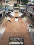
But anyways...here is the deck installed. I ground down all the stringers to fresh glass and put down a healthy amount of hairy PB on all the stingers. My recipe is 25% by volume of chopped strand, 50% by volume of cab, then add MEKP and mix for 2+ minutes. Then, take another 30-50% volume of cab and start mixing it in until the consistency is reached.
Since the original deck was stapled down, I also stapled down the new deck every 6 inches with 1" crown staples.
IMG_7704.JPG
This deck is solid, even over the void above the gas tank. I know some people have concerns with flex at the gas tank void. but I will end up having a bench seat mounted from side to side that will be glassed to the deck. So, this bench will hold the deck "Up" and further reinforce this area.
Oh, and disregard the ugly layup at the gas tank - this was just so I could get CSM wrapped from the bottom around that exposed edge. I will grind the top side off and then wrap a new top layer of CSM down around that exposed edge. The previous deck showed signs of potential rot there because they did not seal this edge.

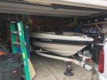
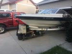
In case anyone is curious, my boat lives in the garage, but comes outside to play with resin. Here is my ghetto transportation system.
IMG_7788.JPG
It works well because I literally have only 1 inch of clearance on every side, so this allows me to take it nice and slow in and out of the garage.
 

kcassells

Fleet Admiral
Joined
Oct 16, 2012
Messages
8,718
Blackened ply usually means rot wet then dry wet then dry....
Always wet out your ply surfaces and edges and let dry prior to glassing or the glass will soak it up and prevent a good bond.
Most times add some chopped strand to underside of deck for waterproofing. It has no strength value.
For piece of mind if you can see it, replace it all on a rehab.
Looks like you moving along pretty well. Like the templates.
 

Capriupgrade

Seaman Apprentice
Joined
Jan 24, 2019
Messages
33
Sorry for the delay in posting! Been crazy with the day job...

Thanks for the feedback kcassells. Anywhere I found blackened wood got cut out, replaced, and reinforced, so I feel comfortable with the repairs. in addition, I drilled exploration holes quite extensively, so I am 99% sure I got all the rot.

No kidding? There is no strength value for putting CSM on both sides of the deck? That is very surprising!

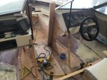
Anyways, to continue with the catch up - In the previous long post I sanded critical areas and then installed the deck. The next step was to frame in all the seating. I chose to frame before I tabbed and fiber-glassed the deck because this allowed me to staple and screw the seating into the new deck without compromising the fiberglass. If you have ever tried to stable /screw into fiberglass coated wood, you probably know what I am talking about - the staple or screw causes a localized area of de-lamination at the impact area (No good!).
sp11.gif
IMG_7733.JPG
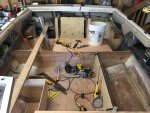
The next step was installing the pillars and framing in the boxes. Not a great picture of the pillars, but I am sure a better view will pop up in future posts. I took these photos before I decided to start this forum posting.
As you can see, there will be a full width rear seat which transitions into a bench seat along the port side, and a single box for the driver seat. Yet to be built at this point are the other two pillars on port and starboard of the rear seat to support the back cushion.
This was an absolute pain in the rear to lay out as there is no square surface in this boat. I ended up pulling a center-line from bow to stern and working off of that. But even that was problematic as the driver and passenger consoles are not centered in the boat. So, I am constantly cheating things a little in either direction to make them look right.
IMG_7731.JPG
Another view of the seat boxes being roughed in. At this point, I am getting ready to frame in the front boxes, but first I had to get the driver and passenger consoles adjusted back at their proper height so that the window closes correctly. This was equally challenging as there are no good common reference points between the two consoles. My original plan was to use the rearward lower corners, but turns out they roughly cut the fiberglass and slapped on the aluminum trim. I can't remember exactly what I finally used as a reference, but I think it was the front top corners by the window (This was a few weeks ago).
IMG_7737.JPG
Now that the consoles are adjusted correctly, time to frame in the front boxes. Templates are your friend!
After everything is framed, my plan was was to come back and grind. On hindsight, I regret that decision...lol!
IMG_7757.JPG
Perfect fit, first time! Only complaint is the plywood was warped and wanted to bow, even though I had it standing in the garage for months. Grrr. Once I add the CSM to both side, it help take out the bow - so long as I can keep it straight while I fiberglass both sides! Worst case, I will add ribs on the insides as needed to take out any bows.
IMG_7759.JPGIMG_7758.JPG
IMG_7765.JPGIMG_7766.JPG
Time to frame in the foot rests under each console.
I saw this feature on a 2019 Bayliner and really liked it. So, in it goes!

IMG_7767.JPGIMG_7771.JPG
Box in the kick panel so that I can have a spot for flotation foam and a little shelf below each console.

IMG_7772.JPG
Cap the boxes and done with the front main framing! Now, off to finishing trimming and grinding....
 

Attachments

  • sp19.gif
    sp19.gif
    1.7 KB · Views: 3
  • IMG_7705.JPG
    IMG_7705.JPG
    1.4 MB · Views: 5
  • IMG_7705.JPG
    IMG_7705.JPG
    1.4 MB · Views: 3
Top