Bravo 3 loss of lube oil - slowly then rapidly x2

dubs283

Vice Admiral
Joined
Jul 27, 2005
Messages
5,322
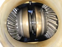
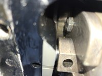
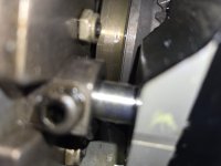
Nothing in the pics posted looks concerning to me

I will say keep an eye on the spacer/shim seen in the first pic. You wanna make sure that's clean and intact prior to reinstalling the u joint/bearing/gear assy
 

gcarmich

Seaman
Joined
Jan 8, 2009
Messages
52
I realized I need a new washer (and nut, maybe) before preloading.
Question - When I align the clutch gear timing marks, do I need any special tools? Like the "Shift handle tool"?
 

alldodge

Moderator
Staff member
Joined
Mar 8, 2009
Messages
42,054
I realized I need a new washer (and nut, maybe) before preloading.
Question - When I align the clutch gear timing marks, do I need any special tools? Like the "Shift handle tool"?
No special tools needed, just align marks per manual
 

gcarmich

Seaman
Joined
Jan 8, 2009
Messages
52
The new washer and nut arrived. I was expecting the washer to be slightly concave with a "NUT" marking on one side but the new one is flat. The video I saw indicated it covered Bravo but maybe the concave washer doesn't apply to Bravo 3?
 

gcarmich

Seaman
Joined
Jan 8, 2009
Messages
52
Can I align the + and - without removing the fork that sits astern of them in the housing? And then insert my drive shaft assembly?
 

Fun Times

Moderator
Staff member
Joined
May 16, 2009
Messages
9,046
Can I align the + and - without removing the fork that sits astern of them in the housing? And then insert my drive shaft assembly?
Dubs touched on this in post number 36,

Also, going back together it'll be easier to verify the +/- offset alignment of the fwd/rev gears.

4. Align clutch gear timing marks with index marks on drive shaft housing as close as possible.
IMPORTANT: Ensure that the retainer nut is not cross-threaded by turning the retainer nut counterclockwise until thread engagement is felt; then turn retainer nut clockwise.
5. Install U-joint assembly into drive shaft housing. Apply Special Lubricant 101 to threads of retainer nut and install. Torque retainer nut to 200 lb-ft (271 Nm)... < Remember to measure Torque Wrench Length in Inches to achieve 200 lb-ft using the chart in the manual.

6. Check that timing marks are still properly aligned (by turning U-joint, if necessary). If marks have moved; remove U-joint assembly and start over beginning with step (3). • Refer to "Special Information" on page 23 if shift cam assembly is being replaced.

Sometimes it takes a few stab's to get the timing marks to align while getting the feel for how they turn when installing the assembly...It can be hard to see in there and depending on how new the stern drive is year/serial number wise?, Some of the newer models 'the lines are even smaller / challenging to see vs the older units. So I'd guess that depends on what you can see with leaving it in there on yours but easier with it out.


What manual number are you using? What year is your drive unit?
 

gcarmich

Seaman
Joined
Jan 8, 2009
Messages
52
Dubs touched on this in post number 36,


4. Align clutch gear timing marks with index marks on drive shaft housing as close as possible.
IMPORTANT: Ensure that the retainer nut is not cross-threaded by turning the retainer nut counterclockwise until thread engagement is felt; then turn retainer nut clockwise.
5. Install U-joint assembly into drive shaft housing. Apply Special Lubricant 101 to threads of retainer nut and install. Torque retainer nut to 200 lb-ft (271 Nm)... < Remember to measure Torque Wrench Length in Inches to achieve 200 lb-ft using the chart in the manual.

6. Check that timing marks are still properly aligned (by turning U-joint, if necessary). If marks have moved; remove U-joint assembly and start over beginning with step (3). • Refer to "Special Information" on page 23 if shift cam assembly is being replaced.

Sometimes it takes a few stab's to get the timing marks to align while getting the feel for how they turn when installing the assembly...It can be hard to see in there and depending on how new the stern drive is year/serial number wise?, Some of the newer models 'the lines are even smaller / challenging to see vs the older units. So I'd guess that depends on what you can see with leaving it in there on yours but easier with it out.


What manual number are you using? What year is your drive unit?
Service Manual #28. I believe the drive unit is 2005 (S/N OW260110)
 

gcarmich

Seaman
Joined
Jan 8, 2009
Messages
52
I've got good visibility to timing marks from both the drive shaft side and the stern end. I think it will work without removing fork. Does 2-4-C replace special lubricant 101?
 

Attachments

  • 20240706_103652.jpg
    20240706_103652.jpg
    3.2 MB · Views: 3
  • 20240706_103156.jpg
    20240706_103156.jpg
    1.1 MB · Views: 3
  • 20240706_103151.jpg
    20240706_103151.jpg
    888.8 KB · Views: 3

Fun Times

Moderator
Staff member
Joined
May 16, 2009
Messages
9,046
I've got good visibility to timing marks from both the drive shaft side and the stern end. I think it will work without removing fork. Does 2-4-C replace special lubricant 101?
Seems you may be good if you're able to align with the marks on the housing... I believe it was 2006 is when they went with smaller, hard to see lines.

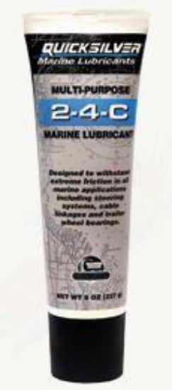
Yes 2-4-C is/was able to be used in place of 101 should it had been needed in the early years too.
Quicksilver 2‑4‑C Marine Grease with PTFE is a high quality, extremely versatile lithium‑based, NLGI 2 grease that won’t break down when mixed with water. It also has:
• Excellent resistance to oxidation and degradation
• Extreme pressure additives to withstand friction in a wide variety of
operations and temperatures
Replaces Quicksilver Special 101 Lubricant part number 92‑802865Q02
For use in the following marine applications:
• Steering systems/cable linkages
• Throttle and shift cables and linkages
• Remote controls
• Prop shafts
• Swivel pins
• Tilt lock mechanisms/tilt tube
• Hinge pins
• Boat trailer wheel bearings
 

gcarmich

Seaman
Joined
Jan 8, 2009
Messages
52
The u-joint assembly does not want to go in all the way. I can get it to about 1/2 inch of the ring but it doesn't want to go beyond that point. Had a difficult time removing it also. Any tips on getting the u-joint assembly back in all the way?
 

alldodge

Moderator
Staff member
Joined
Mar 8, 2009
Messages
42,054
The timing marks should be aligned as seen from the rear, not the front
The shift fork and shift shaft should be removed in order to align timing marks, can be done without removal but makes it more difficult and may be in gear which would be bad

Note alignment marks on bottom pic

Slide4.JPG
 

alldodge

Moderator
Staff member
Joined
Mar 8, 2009
Messages
42,054
Did you get correct rolling torque?
Check the threads, might have been some galling
 

gcarmich

Seaman
Joined
Jan 8, 2009
Messages
52
Did you get correct rolling torque?
Check the threads, might have been some galling
Yes. Set rolling torque with dial meter to appropriate range for reusing bearings.
Can't get it inserted as far as the threads on the retaining ring. Can only get to o-ring. Then it seems to stick. I've got pretty good visibility from behind. I don't have tool for removing fork.
 

Scott06

Admiral
Joined
Apr 20, 2014
Messages
6,423
Yes. Set rolling torque with dial meter to appropriate range for reusing bearings.
Can't get it inserted as far as the threads on the retaining ring. Can only get to o-ring. Then it seems to stick. I've got pretty good visibility from behind. I don't have tool for removing fork.
Did you grease the oring ? Or is it rolled. I forgot to grease the prongs on my driveshaft and had a hell of a
Time getting drive on… a little grease and good to go
 

alldodge

Moderator
Staff member
Joined
Mar 8, 2009
Messages
42,054
Yes. Set rolling torque with dial meter to appropriate range for reusing bearings.
Can't get it inserted as far as the threads on the retaining ring. Can only get to o-ring. Then it seems to stick. I've got pretty good visibility from behind. I don't have tool for removing fork.
Check for burrs and the use some grease like 2-4-C

Easy to remove the shaft without special tools
 
Top