96 5.7L Mercruiser - no compression, water in

96RinkerCaptiva212

Petty Officer 3rd Class
Joined
Jun 4, 2017
Messages
84
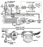
Rick - when you say sealed solenoid switch, is this what I keep reading about when people are saying "relay". It seems like I'm reading the parts on other threads as relay, oil pressure switch and fuse. Are you referring to something like this?
 

96RinkerCaptiva212

Petty Officer 3rd Class
Joined
Jun 4, 2017
Messages
84
No Title

Also, got the LB in and have the RTV setting up now with the intake! Now I won't be able to focus on work today.. is it bad that I have a friend coming through from out of town and he wants to hit a Reds game and all I really want to do is skip and keep working at the boat? :facepalm:
 

Attachments

  • photo269053.jpg
    photo269053.jpg
    46.2 KB · Views: 0

Rick Stephens

Admiral
Joined
Aug 13, 2013
Messages
6,118
The fuze or circuit breaker for a fuel pump is something like a 10 amp, lots smaller than that big circuit breaker you have. Your pump will have come with instructions on what amp the fuze should be.
 

96RinkerCaptiva212

Petty Officer 3rd Class
Joined
Jun 4, 2017
Messages
84
No Title

Update - got quite a bit done today as far as putting the top end together and accessories. I went and got an adapter for the spread bore intake to straight bore carb. Got extra intake holes plugged up, power steering and alternator back on, hoses on, acetone test on exhaust was good. New starter came in and put that on. As I was putting carb on, I realized by 2 barrel throttle bracket will not fit on this new Holley 4160!! CRAP!! And here I thought I just might actually make it for July 4th!

So, I see a ton of throttle bracket kits but doesn't actually look like what I need to stabilize it on the carb. I did find one on Ebay from a 4 barrel so I guess that is all I would actually need but it won't deliver until 7/10!! I think I might just wait until Monday and call some Marine shops around here and ask if they have any 4 barrel arms for sale. Almost tempted just to make my own tomorrow out of some steel stock. I wonder what my 2 barrel arm is made out of? could probably cut the arm from the base of it with the 2 carb mount holes and just weld in a new plate? Dissapointed running into this one.
 

Attachments

  • photo269209.jpg
    photo269209.jpg
    96.8 KB · Views: 0

96RinkerCaptiva212

Petty Officer 3rd Class
Joined
Jun 4, 2017
Messages
84
No Title

Update - got the engine aligned. The tool slipped in pretty easy but I would describe the grease/spline markings as great on the bottom and not perfect on top. Outdrive was difficult to get started but driveshaft slipped in well once I got it to the coupling. Replaced the larger o-ring for the housing, water inlet o-ring and assembly gasket. I actually think it was not aligned when I pulled it originally. That thing was a BEAR getting out of the coupler during removal. I'm awaiting arrival of throttle bracket, Gas-Dry(stabil) and spark arrestor for 4 barrel. I will start on the fuel pump wiring I think as the relay switch came in as well. Need to go get a inline fuse holder, wires and terminals/shrink tube. Questions:

1) See pic of starter wiring - got the new starter installed but there are no instruction from DB Electric as to where this yellow/red wire goes. This starter unit has two smaller posts straight across from each other (under red cap in pic). No markings around either post. Maybe it can go to either. Any thoughts?

2) Disty pic - this is how I found it upon removal with cylinder 1 at TDC. I marked it here in white. I see now I was looking at the spring button instead of the extended post (pointing at #6 in the pic) that would be making contact with the terminals inside/under the disty cap. It would appear this was 180 degrees off but my friend says it was probably just 1 revolution off during the compression stroke. So it wasn't really much out of time at all. Can anyone confirm that? It's just driving me nuts that I literally can't figure out what actually caused the 4 pistons to detonate.

3) Fuel Pump - Is 14 gauge wire good enough? I have 10 feet of flexible USCG approved fuel line coming thursday or Friday. I can actually use that on the entire fuel setup, right? It seems like the posts I read are a mix bag. Flexible and Hard being used. This is my first carb vehicle/vessel but my dad has always had flexible line with no issues. Just looking for watchouts. Obviously, I need to grab some barb fittings and clamps
 

Attachments

  • photo269411.jpg
    photo269411.jpg
    81.2 KB · Views: 0
  • photo269412.jpg
    photo269412.jpg
    83.1 KB · Views: 0

Rick Stephens

Admiral
Joined
Aug 13, 2013
Messages
6,118
No way that a starter manufacturer can send you wiring instructions. Wire colors and wiring routing is all application specific. The Yellow/Red goes to the inner solenoid stud - the one towards to engine. That stud engages the solenoid and powers the starter.

The outer small stud is to power the fuel pump when the starter is cranking.

Can't speak to timing question. If in doubt, turn engine to #1 TDC, point rotor to #1 spark plug wire and reset timing when you start it up.

14g should be fine.
 

96RinkerCaptiva212

Petty Officer 3rd Class
Joined
Jun 4, 2017
Messages
84
No way that a starter manufacturer can send you wiring instructions. Wire colors and wiring routing is all application specific. The Yellow/Red goes to the inner solenoid stud - the one towards to engine. That stud engages the solenoid and powers the starter.

The outer small stud is to power the fuel pump when the starter is cranking.

Can't speak to timing question. If in doubt, turn engine to #1 TDC, point rotor to #1 spark plug wire and reset timing when you start it up.

14g should be fine.

Ok, cool - so I actually have a free stud available for this pump install. Didn't realize that. Thanks for your help! I'm sure I'm about to have a few more on the pump process. The extent of my wiring knowledge is replacing outlets in my house and a ceiling fan, lol.
 

Rick Stephens

Admiral
Joined
Aug 13, 2013
Messages
6,118
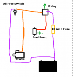
Here's a basic drawing of the wiring.

Orange comes from that outer lug on the starter and joins the wire going from oil pressure switch to the switch on the relay. That way either the starter or the oil pressure switch can turn on the relay to power the pump.

Purple is battery power.

Red is switchable power from the relay to the pump positive side.

Green ground.

Screen Shot 2017-07-04 at 1.33.10 PM.png
 

96RinkerCaptiva212

Petty Officer 3rd Class
Joined
Jun 4, 2017
Messages
84
Here's a basic drawing of the wiring.

Orange comes from that outer lug on the starter and joins the wire going from oil pressure switch to the switch on the relay. That way either the starter or the oil pressure switch can turn on the relay to power the pump.

Purple is battery power.

Red is switchable power from the relay to the pump positive side.

Green ground.


that drawing is incredibly helpful! :victorious: It's making more sense now. I just got back from O'Reilly with 3 colors of 14 gauge wire, assorted terminals and a 10 amp inline fuse holder. The guy said I need to look on Jegs for a NO oil pressure switch and they wouldn't have what I'm looking for. I didn't realize I needed a two prong switch. I was shooting for a single attachment like my oil pressure sender on the back of the block. that's clear now. Really just seems like there would be a vehicle with the switch I'm looking for. Getting ready to go meet family so I'll research that later. I don't really want to wait another couple days on amazon to kick me the dual prong switch but oh well. It's just holding me up from installing the disty.

found a carter unit that kicks on at 7psi - has 3 prongs

https://www.summitracing.com/parts/crt-a68301
 
Last edited:

96RinkerCaptiva212

Petty Officer 3rd Class
Joined
Jun 4, 2017
Messages
84
I guess it's the different versions that's confusing me since they all seem to have a slight difference. That's a newB talking though, lol. This one is pretty detailed. I just went to locate and mount the relay to the transom wood so I can tell how long all the wires really need to be. I have the 87 terminal in the relay going right to the + terminal on the fuel pump and now I'm off to see some more fireworks. Hoping the rain holds out tomorrow so I can wrap this wiring up. the oil pressure switch that's coming in tomorrow has 3 terminals (p for power from relay, I for ignition and S for Starter). It seems we haven't discussed tying into the ignition. Should I just leave the "i" post empty?

2nd question - how does one actually tie in. Like I need to splice the starter lug wire into the relay-to-oil pressure wire. You just "T" that in? I wasn't seeing a T-terminal at the store. Or is it more like attach both wires into the wire terminal that is plugging into the 86 relay terminal? I'm searching around the net and not really running to how to PROPERLY do this. I mean, I can cut some insulation off and wrap the wire around and solder it but I'm not sure that's "correct". elecpump04.jpg
 
Last edited:

96RinkerCaptiva212

Petty Officer 3rd Class
Joined
Jun 4, 2017
Messages
84
throttle.jpg I lost most of the day in the throttle linkage bracket that I ordered. It's obviously for a car/truck with a kickdown attachment and I couldn't figure out how to get the very end of the mercruiser throttle mount off the cable to mount it just like a car. also didn't have the clip that would lock it into this red bracket. I worked it up still using the mercruiser end and that adjustment piece. throttle lever action seems good on it. I need to get the gear selector unit mounted on the exhaust and recheck it though. Lever at neutral has the carb butterfly completely closed. Lever at WOT maxes out the carb with still some room for adjustment so I think that will work.
 

96RinkerCaptiva212

Petty Officer 3rd Class
Joined
Jun 4, 2017
Messages
84
Here's a basic drawing of the wiring.

Orange comes from that outer lug on the starter and joins the wire going from oil pressure switch to the switch on the relay. That way either the starter or the oil pressure switch can turn on the relay to power the pump.

Purple is battery power.

Red is switchable power from the relay to the pump positive side.

Green ground.


Rick, can you confirm I have everything correct or tell me what is remaining at this point? The 3 prong oil switch is throwing me off a bit (that crude drawing you posted shows two points of contact). I've been putting this off but decided to jump in today. Here is what I have completed:

Relay:
86 - To Oil Pressure Switch P Terminal (i'm not sure this is correct, I thought 86 had to be connected to battery power)
85 - Grounded to Coil Negative Post
87 - Straight to fuel pump
30 - To Battery Positive with 10 amp fuse in between
87A - unused

Oil Pressure Switch:
P Terminal - connected to 87 on relay (instruction says run to pump actually, not confident here)
S Terminal - connected to outer Starter Lug
I Terminal - I don't know what to do with this. Most drawings don't mention ignition with marine setups. Instructions and that detailed breakout I posted says go to Ignition.

Pump:
+ terminal is connected to 87 Relay post
- just attached a connector and grounded it to a bolt on the front cover, which is holding the fuel pump bracket

**10 foot of USCG approved marine fuel line just came in so I'm going to head to the hardware store and get some barbed fittings for everything.
 
Last edited:

Rick Stephens

Admiral
Joined
Aug 13, 2013
Messages
6,118
85 ground
87 to the fuel pump
86 from the pressure switch and the starter
30 to purple power wire - I want this to turn off when I switch off the ignition. Hence connect to the purple wire.

So YEAH! You got it right on.


I have never used a three pole pressure switch. Test it. You can probably ignore the third pole.
 

96RinkerCaptiva212

Petty Officer 3rd Class
Joined
Jun 4, 2017
Messages
84
85 ground
87 to the fuel pump
86 from the pressure switch and the starter
30 to purple power wire - I want this to turn off when I switch off the ignition. Hence connect to the purple wire.

So YEAH! You got it right on.


I have never used a three pole pressure switch. Test it. You can probably ignore the third pole.

You're referring to the purple wire going to the alternator, correct? So rather than me going from Battery to 30, go from Alternator to 30. I don't have a purple wire going to the battery if that was some type of factory setup. I just don't want to burn my boat down, haha.

For the 3 post switch. P and I are normally closed according to the instructions. So in my head if the starter is powered for cranking, it will move to the P and S open position.. I think I'm saying that right. :lol: I guess I'm unclear if attaching I to the ignition source changes anything...
 

Rick Stephens

Admiral
Joined
Aug 13, 2013
Messages
6,118
Makes sense that you could attach the starter to the spare post. Try it.

Purple comes through the big plug that powers the engine. It is ignition power. You should be able to grab it near the slave solenoid for the starter. Main thing is, we want switched power so the fuel pump is dead when the ignition is off. So wherever you get power, should be a purple wire and should go off with the ignition.

Rick
 

96RinkerCaptiva212

Petty Officer 3rd Class
Joined
Jun 4, 2017
Messages
84
Makes sense that you could attach the starter to the spare post. Try it.

Purple comes through the big plug that powers the engine. It is ignition power. You should be able to grab it near the slave solenoid for the starter. Main thing is, we want switched power so the fuel pump is dead when the ignition is off. So wherever you get power, should be a purple wire and should go off with the ignition.

Rick
I grabbed the purple wire coming from the main harness from the front, before that large black plug on the engine. I spliced it over to the ignition terminal on the oil pressure switch. And then as we were talking, instead of running the 30 terminal (inline fuse) straight to the battery, I spliced it into the purple wire going to the alternator. I think this completes everything I need to do for the fuel pump. Fuel hoses are all hooked up now so it's ready to be tested.

I have one more wiring question. I thought this carb I got from Rapido was a Holley 4160. What I'm seeing searching around, it doesn't have dual fuel ports on the same side. Anyway, it's a 600cfm holley and it has 2 hookups on the choke. My old 2 barrel only had the positive choke thermostat hookup. Seems like I need to run a ground wire here and run it to a screw somewhere, correct? I have 2 ground wires coming out of the smaller wiring harness but I think that's for the throttle bracket somewhere. Kicking myself for not taking a pic of this setup or some notes. I'll keep poking around on it.

Last question, there is a smaller brass port to the left in the pic. Seems to be an air intake port of some sort. Should I be running a hose to something? I don't see another port/opening on the carb. Do I run this to PVC? I see it is a Choke Fresh Air port, but not seeing what it supposed to be hooked up to.

SO CLOSE!! I just went and bought a timing light. I can't quite get the rotor point dead nuts at cylinder 1 but it's very close. I think it's the cam gear pulling it around but I have #1 on TDC so can't really move it. Sorry, throwing a whole bucket of thoughts at you, haha.

4160 port.jpg
 

Rick Stephens

Admiral
Joined
Aug 13, 2013
Messages
6,118
You won't have any problem running a ground wire from the minus tab to any convenient ground nut on the motor. The motor is well grounded.

Is that brass vent into the choke? Might be some sort of convertable heat riser fitting. I have no idea what else it might be. Too low for dumping a failed mechanical fuel pump overflow line...

If you stabbed the disty near TDC, next is to spin it up and set the timing. Can't get it much closer just by eyeballing it. Highlight your marks with chalk or white paint and you can set timing even before the motor starts. Good timing light will fire while you crank letting you nail it down.
 
Top