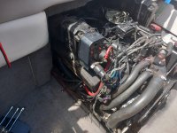
1996 Four Winns Sundowner with 5.0 Cobra engine and drive

Lou C

Supreme Mariner
Joined
Nov 10, 2002
Messages
12,679
Thanks, I don't know how the dashboard is wired up but it occurred to me that if the ign on wire connects to the ign switch at the front of the boat (as opposed to coming from a relay at the rear), then if the ignition switch gets power from the same wire that runs to the front to power other stuff like lights etc any voltage drop on that wire would result in the batteries getting too much charge... Hence my question about running a separate wire from Vsens on the alt direct to the battery isolator switch.

S terminal being the unswitched starter terminal?
On the ignition switch:
terminals:
B=battery, red wire should show battery voltage when battery switch is on
I=ignition, purple wire should show battery voltage when key is turned to ignition on (1st notch from off)
S=start, yellow red wire, this should get battery voltage when you turn it to start.
that same yellow red wire runs to a relay on the engine somewhere and then down to the S terminal on the solenoid.
 

Lou C

Supreme Mariner
Joined
Nov 10, 2002
Messages
12,679
When I knew first found out my engine needed a rebuild then read about OMC Cobra parts being difficult to source I thought about the feasibility of converting my setup to a half closed system, that way I could just fit a truck engine and not need to worry about marine cooling system components other than the exhaust manifolds which I soon found out I could still easily buy.
You could have done that, a normal 5.0 Ford V8 out of a Mustang or F-150 pick up is basically what you have.
About adding closed cooling, you can if the internal cooling passages are clean and not rusted, but not if it has been run in salt or brackish water, because of the way cast iron rusts, it flakes off and that will clog the internal passages of the heat exchanger.
 

Lpgc

Petty Officer 1st Class
Joined
Jun 17, 2023
Messages
258
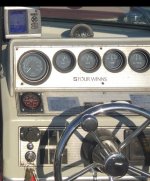
Thanks @Lou C . I still haven't taken pics of the dashboard, which has car like instruments (as opposed to individual gauges mounted separately on say a wooden dash). Did notice today that the voltmeter is all the way over to 18v without a battery connected, is that normal or is the voltmeter broke? If any of the gauges in the car like panel are broke can they be individually repaired or is the panel similar to a modern car with a PCB that all the instruments are mounted to?

Spent a bit of time in the boat today mostly just trying to see if I can find where all the wires are supposed to run to and route around the engine. During removal I took pics and stored them in a folder on the laptop, today I collated all pictures showing wiring that might be useful for putting the wiring back on into a single folder so tomorrow I can take the laptop on the boat and the pictures should help with putting it back together.

Seems I didn't take many useful pictures showing where on the engine the earth straps connect to or how the PAS cooler bolts on and water pipe routing for the PAS cooler. If anyone has any pics of how the wiring should look at the back of the engine or how the PAS cooler is bolted on I'd appreciate seeing them. I suppose it doesn't much matter where most of the main earths connect at the rear of the engine but I have some specific questions such as does an earth need to connect directly to a starter motor mounting bolt?

@alldodge I forgot to reply re helicoils and 'thin serts'. I've used helicoils before but the hole is broken (as in my picture in a post above) so I don't think a helicoil could fix this. Sorry if this is a daft question but is thin serts a typo for time sert, something I've not heard of that could be useful, or another example of difference in terminology between Brit and American English?
 

alldodge

Moderator
Staff member
Joined
Mar 8, 2009
Messages
42,064
@alldodge I forgot to reply re helicoils and 'thin serts'. I've used helicoils before but the hole is broken (as in my picture in a post above) so I don't think a helicoil could fix this. Sorry if this is a daft question but is thin serts a typo for time sert, something I've not heard of that could be useful, or another example of difference in terminology between Brit and American English?

Sorry it came out wrong meant to say threaded inserts
https://www.amazon.com/16-14-Chevy-thread-repair-0761D/dp/B00TG25CME

Not sure the housing can be fixed. Might be able to fabricate something to mount on top side and thread to hold. Maybe something that goes around most of it to get enough holding power. Don't know but maybe a big washer and nut
 

Lpgc

Petty Officer 1st Class
Joined
Jun 17, 2023
Messages
258
Sorry it came out wrong meant to say threaded inserts
https://www.amazon.com/16-14-Chevy-thread-repair-0761D/dp/B00TG25CME

Not sure the housing can be fixed. Might be able to fabricate something to mount on top side and thread to hold. Maybe something that goes around most of it to get enough holding power. Don't know but maybe a big washer and nut
I was thinking along the same lines as a nut underneath and something around it (maybe like a jubilee clip) to prevent the bolt that goes through the broken hole (or the nut) going outwards and it coming undone. Did think about grinding the underside of the broken part at an angle and using a tapered washer on the underside which could prevent the bolt coming out of the hole sideways but grinding could weaken the housing further. Seems someone in the past just mig welded a nut to the cast iron and it held until I tapped the bolt to try to unsieze the housing from the bolt, I could try welding it but I don't really want to risk it. Not too worried about the broken bolt hole though, confident I'll be able to effect a fix some way, just a nut with a flat washer might even do it.

I had a look at the link you posted, heh the Amazon advert mentions using the time sert kit to repair head bolts, I've never used a time sert but the first time I used a helicoil was to repair the rocker carrier thread on a VM diesel 2.5 engine when a rocker stud pulled out of a cylinder head. The VM diesel is a strange engine designed for marine and machine (like generator) use but was fitted as original engine in some vehicles, weird because some versions have a separate cylinder head for each cylinder.
 
Last edited:

alldodge

Moderator
Staff member
Joined
Mar 8, 2009
Messages
42,064
Repaired 454 block last year with a time sert and like it much better then helicoil
 

Lpgc

Petty Officer 1st Class
Joined
Jun 17, 2023
Messages
258
Just dropped a 5/16 1/4drive socket I was trying to use to tighten the J clip holding the raw water pump pipe to the rear of the transom stuff into (I think) the area between the coupler and the transom stuff. Going to try to use a borescope now to try to find it and fish it out with a magnet. Worst case scenario I'll need to lift the engine again to remove it :-(
 

Lpgc

Petty Officer 1st Class
Joined
Jun 17, 2023
Messages
258
Just dropped a 5/16 1/4drive socket
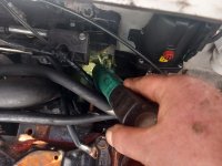
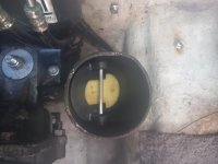
Found it with the borescope, it had fallen down the hole I'm shining a torch at in the picture below, got it out with a magnet pick up tool :)

20240426_164726.jpg

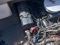
Since then I've fitted the wiring to the new alternator, confident I got it right. Tightened the J clip on the water inlet, connected the water pump inlet pipe to the bottom of the PAS cooler. There's 3 broken wires, I know where 1 of them is supposed to connect but I need to work out where the other 2 are supposed to connect to, I'll be looking through pics I took before starting the engine removal to see if they'll help. Different issue to the broken wires the engine hour meter became disconnected from its 2 spade connectors and I'm not sure which spade connects to which side of the hour meter (polarity).

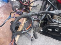
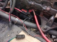
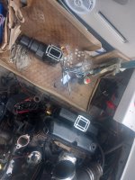
Don't know where the purple wire in the 1st picture below is supposed to go, maybe it goes into the same spade as the other purple wire which connects to the hour meter? I suspect the brown wire was connected to the blue wire in the 2nd picture below. I connected the female spade with the purple wire to the hour meter but I don't know if it's connected to the correct male spade on the hour meter.

20240426_185157.jpg

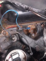
I know where the brown with black stripe wire is supposed to go. This is the blue wire I believe the brown wire in the above pic is supposed to connect to.

20240426_185209.jpg

Seems there are 2 temp sensors in the inlet manifold, obviously one is for the dash temp gauge but what is the other one for (is it part of the automatic electric choke system)?
 
Last edited:

Lpgc

Petty Officer 1st Class
Joined
Jun 17, 2023
Messages
258
I think I've found out where the wires are supposed to go by looking through pics I took before and during engine removal...

Both purple wires to the hour meter, the brown to the blue
20230623_133705.jpg 20230626_140200.jpg

Seems the first pic even shows which way around the 2 wires connect to the engine hour meter.

If I'm right about this I might not need to ask any more questions about wiring :D
 

Attachments

  • Starter motor 20230709_175612.jpg
    Starter motor 20230709_175612.jpg
    2.9 MB · Views: 3
Last edited:

alldodge

Moderator
Staff member
Joined
Mar 8, 2009
Messages
42,064
Good deal on socket retrieval

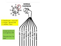
Purple is powered up from the key switch. When key turns ignition ON and sends power to all gauges and back to the motor on pin 5. The broken wire appears to be close to the 10 pin connector, see if there is a purple attached.

Brown is actually a Tan wire and it goes to the temp send, one on left with Blue wire attached

The other sender may be a switch. If it is a switch then it will ground when over heated and sound a alarm. It's not for electric choke
 

alldodge

Moderator
Staff member
Joined
Mar 8, 2009
Messages
42,064
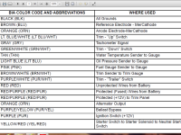
colors
 

Attachments

  • Merc Color Codes.png
    Merc Color Codes.png
    256.5 KB · Views: 3
  • 10 Pin Jump start.jpg
    10 Pin Jump start.jpg
    56.3 KB · Views: 3

Lpgc

Petty Officer 1st Class
Joined
Jun 17, 2023
Messages
258
Good deal on socket retrieval

Purple is powered up from the key switch. When key turns ignition ON and sends power to all gauges and back to the motor on pin 5. The broken wire appears to be close to the 10 pin connector, see if there is a purple attached.

Brown is actually a Tan wire and it goes to the temp send, one on left with Blue wire attached

The other sender may be a switch. If it is a switch then it will ground when over heated and sound a alarm. It's not for electric choke

I was relieved to dig out the socket. As it turned out, it wouldn't have hurt anything where it was but I didn't know that before I found it, thought it had fallen between the coupler and housing where it could maybe have caused damage.

It makes sense for the engine hour meter to connect to the wire that's powered up with ign key on. I don't know if the hour meter was standard, an option or fitted aftermarket. Maybe they just cut the purple wire, stuck the 2 ends into a spade connector and connected it to the positive side of the hour meter...?

Seems there's another mod been done that I haven't mentioned before now. The tan wire is T'd to a single core green wire that runs all the way to the dashboard but doesn't look standard. I wonder if someone had an aftermarket temp gauge on/near the dash fitted at some time, or tried to fit some other equipment and made a wiring mistake. I cut the green wire to help untangle and make sense of the loom but it will be easy to connect it again. When I've got it mostly all back together, before I try to run the engine I'll run some tests to see if the dash gauges work and try to find out what the green wire mod was for, see if the other 'temp sender' causes an over temp alarm to sound.

Thanks again for all your help.
 
Last edited:

Lpgc

Petty Officer 1st Class
Joined
Jun 17, 2023
Messages
258
Is it better to fit the ancillaries (raw water pump, alternator, pas pump) first or fit the exhaust manifolds first? I don't know if fitting some stuff before other stuff prevents access to bolts etc.

Recently fitted the rocker covers properly, I lifted the engine in with the rocker covers just resting in position.

Changed the flappers. The existing flappers were not burned up and still had all rubber underneath but they were showing signs of a bit of heat (and/or age) damage and were stiff to move on the pins. The stiffness concerned me because I imagine if the flappers get stuck in the closed position they could prevent exhaust gas and water from going out and the water could back up all the way to the exhaust ports of the engine?

On one side of the engine the flapper had kind of stuck to the rubber gromits. I ordered some new rubber gromits but they haven't arrived yet, the original gromits seem OK and I want to move on with the rebuild so I reused the existing gromits. I cleaned the pins and the holes in the exhaust the grommits sit in.

Seems good now, the flappers move easily, I've posted a pic below just to check with you guys that I've put them in the correct way around etc. The pic is of the port side, I fitted the starboard side mirror image. It's a good job the flappers have water flowing past them with the exhaust gas because it seems they'd melt in seconds if there were no water flowing. There are gaps around the edges of the flappers, it isn't as though they make a tight seal all the way around the inside of the exhaust... begs the question why they make them from fibreglass with a rubber coating instead of from metal that wouldn't burn up...

20240430_131940.jpg
 
Last edited:

Lpgc

Petty Officer 1st Class
Joined
Jun 17, 2023
Messages
258
Got a bit more done today, fitted the starboard side exhaust manifold, riser and rubber exhaust pipe. Still haven't fitted the alternator but glad I didn't, seems it's wiring would be better routed from the other direction to the way I currently have it connected because when I put it in position the wires were a bit bunched up against the water pump.

First cleaned the paint off the riser and manifold mating faces using a gasket scraper, cellulose thinners then carb cleaner. Used some RTV below and above the gasket.

20240501_160922.jpg

Not pictured, I cleaned corrosion/crud from where the water/exhaust metal bits connect to the rubber pipes (from both the metal and the inside of the rubber). Obviously no need to do that on the new riser.

20240501_182432.jpg

20240501_182447.jpg

Got it wrong the first time I temporarily fitted the exhaust manifold, didn't realise it used 5 long bolts and 3 short bolts, also didn't realise the new Barr manifold came supplied with 5 long bolts and 3 short bolts lol. Finally fitted the manifold using 2 x long stud to help locate the gasket, 3 long bolts and 3 short bolts.

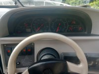
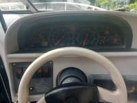
Remembered to take a picture of the instruments. I think the voltmeter is broken because there's no battery connected but it's reading 16volts lol, or is that what they do? Same with the trim gauge, the needle is all the way over but no battery connected. IIrc the fuel gauge, temp gauge, oil pressure gauge and fuel gauge didn't work but the speedo, trim gauge and revcounter seemed to work. The oil pressure gauge not working could've been due to a broken sender, in which case I hope to have fixed it because I found the old sender was broken and fitted a new sender. Seems someone has connected an extra wire (green wire shown in the pic above) to a temp sender, the green wire runs all the way to the front. I cut the green wire to help untangle the wiring but will reconnect it if the temp gauge doesn't work when I have it back together. If broken how serviceable is the instrument cluster? Is there a common feed that the oil pressure gauge, coolant temp gauge and fuel gauge all rely on?

20240501_182738.jpg
 

Attachments

  • 20240501_182747.jpg
    20240501_182747.jpg
    2.4 MB · Views: 3
Last edited:

Lpgc

Petty Officer 1st Class
Joined
Jun 17, 2023
Messages
258
My second post this evening, I asked a few questions in my last post.

I forgot to ask about part numbers for the 3 x V belts on my setup... I watched a Youtube video of someone changing the belts on the same setup as mine
and he mentioned 3858462 is the PAS belt, 3852348 (I don't know if that's the alternator or raw water pump belt), he didn't mention the part number for the 3rd belt. Can anyone tell me part numbers for my 3 belts?
 

alldodge

Moderator
Staff member
Joined
Mar 8, 2009
Messages
42,064
Don't know what to say about the gauges but if power is not applied and they are all the way over, most likely they will need replaced

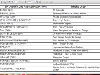
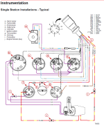
So far as wiring, need to use the ABYC color coding
 

Attachments

  • Merc Color Codes.png
    Merc Color Codes.png
    256.5 KB · Views: 4
  • Helm wiring 2.png
    Helm wiring 2.png
    140.4 KB · Views: 4

Lpgc

Petty Officer 1st Class
Joined
Jun 17, 2023
Messages
258
Don't know what to say about the gauges but if power is not applied and they are all the way over, most likely they will need replaced

So far as wiring, need to use the ABYC color coding
Thanks. This is a 1996 OMC Cobra / Ford 302 / Volvo SX, is the wiring the same?
 

Lou C

Supreme Mariner
Joined
Nov 10, 2002
Messages
12,679
If you go over to:
www.ifourwinns.com
There are a few discussions of that all in one dash panel and some of the problems & solutions. Some replaced the whole thing with a custom panel with separate gauges.
In my boat the 36 year old Medallion gauges all still work!
 
Top