1996 Four Winns Sundowner with 5.0 Cobra engine and drive

Lpgc

Petty Officer 1st Class
Joined
Jun 17, 2023
Messages
258
If it was mine I would remove, it's not needed.
I nearly did decide to remove it, gave it a hard enough tug thinking it would come off but it didn't. I could obviously remove it by tugging harder or cutting it off but when it didn't come off with the tug I thought it's obviously meant to be there. It would be more difficult to access it now the engine is fitted, I've left it with the pipe just loose in the bilge. I don't think it's necessary but I'm still wondering what it's supposed to be for, maybe for a carb breather/overflow?
 

dubs283

Vice Admiral
Joined
Jul 27, 2005
Messages
5,322
I'm still wondering what it's supposed to be for, maybe for a carb breather/overflow?

It's a drain hose for any water that happens to get inside the flywheel cover. Idea is that if water does get into the area that drain will allow water to escape faster so it does not reach the starter or rms/less water being flung around by the flywheel

Superfluous? Maybe, but it's there. Fairly common on certain vintage volvo engines

Leave it or remove it. The choice is yours
 

Lpgc

Petty Officer 1st Class
Joined
Jun 17, 2023
Messages
258
It's a drain hose for any water that happens to get inside the flywheel cover. Idea is that if water does get into the area that drain will allow water to escape faster so it does not reach the starter or rms/less water being flung around by the flywheel

Superfluous? Maybe, but it's there. Fairly common on certain vintage volvo engines

Leave it or remove it. The choice is yours
Thanks.

I can understand the drain but not why it needs a length of pipe/hose attached to it... it would drain into the bilge without the pipe and the pipe needs to run to lower than the bellhousing or the drain won't work, the only place lower than the bellhousing is the bilge.
 

Lpgc

Petty Officer 1st Class
Joined
Jun 17, 2023
Messages
258
I just checked the raw water pump, removed the 3 bolts to check the impellor etc. It seems in good condition and it turned easier with the rear cover removed so it seems the bearings are OK. Put it back together without damaging the gasket.
 

Lou C

Supreme Mariner
Joined
Nov 10, 2002
Messages
12,650
Nice work!
I looked thru my OMC Cobra shop manual for the torque spec on the nuts that hold the coupler on the studs in the flywheel and they give 40-45 ft lbs.
You can see 3 advantages that the Ford engines had over the GM engines...
1) oil filter up front don't need the complication of a remote oil filter mount
2) starter bolts go in parallel to the block not in the bottom, easier than on GM
3) distributor is up front
Yep that rubber hose on the bell housing is just to drain water out, mine has it too, not sure why they felt it was needed.
 

Lpgc

Petty Officer 1st Class
Joined
Jun 17, 2023
Messages
258
Nice work!
I looked thru my OMC Cobra shop manual for the torque spec on the nuts that hold the coupler on the studs in the flywheel and they give 40-45 ft lbs.
You can see 3 advantages that the Ford engines had over the GM engines...
1) oil filter up front don't need the complication of a remote oil filter mount
2) starter bolts go in parallel to the block not in the bottom, easier than on GM
3) distributor is up front
Yep that rubber hose on the bell housing is just to drain water out, mine has it too, not sure why they felt it was needed.
Thanks. I didn't use a torque wrench but it felt like I tightened the coupler / flywheel nuts to around 45ft/lbs.

I haven't had time to do much with the boat since my last post. Around the time of my last post the weather was really changeable, I was getting fed up of starting some work on the engine in good weather only for it to start raining heavily. Then I thought I'll just put the bimini / weathe cover on then I can work inside and stay dry (and the engine and carpet stay dry) even if it rains. Heh, I'd forgotten which way the poles fitted for the bimini and it took me over an hour to put it up. There was always 1 pole missing, a length of around 2.5ft 22mm OD x 1.5mm wall thickness polished stainless tube which I've bought but not yet fitted. There were also a few pins missing which I've bought and have fitted (except for the pins for the missing tube).

Did a bit of head scratching trying to work out how the alternator and tensioner bracket fitted, watched a Youtube video showing a guy changing the V belts and found the bracket fits to the front of the water pump. I had already fitted the WP using new stainless bolts so I needed to remove those 2 WP bolts I'd already fitted to fit a couple of longer bolts that would reach through the tensioner and WP. Today I visited a local bolts specialist firm who gave me an assortment of bolts and I got the bracket fitted.

Having fitted the alternator bracket I decided to change the thermostat. Problem is although the thermostat housing is OK the cast iron elbow it bolts to had already been repaired where one of the bolt holes (for the longer bolt) had broken, there's supposed to be a hole there but there's just half a hole with the outer part broken off. Someone had tried to repair it in the past by welding a nut to the cast elbow but the weld broke when I removed the housing. There's still half the hole remaining so it looks like there's enough material for a nut to pull on and I should be able to effect a fix but I'd probably buy another elbow if I could find one. I can easily buy a new housing but seemingly not the elbow. I've ordered mixed wire wheels to attach to the drill / dremmel to clean up the inside of the housing before I fit the new thermostat in it, also ordered some JB weld in case it helps fix the mouting hole on the elbow. I realise it's hard to advise without seeing pics (and I should have taken some to post here) but would appreciate any advise on how to effect a fix of the broken bolt hole in the elbow..? The design of the way the thermostat fits doesn't look very secure just held in with a rubber O ring, in the video I watched the guy helps make sure it seals and is secured by using some sealant under the 'stat and around the O ring, any advice on that?

I think my next question (after the one above) will be on how to wire the alternator. The alternator I removed worked fine but I think I broke it during removal when a connector sticking out the back of the alternator worked loose when I unscrewed the nut that secured a wiring connector to the back of it... so I bought a new one. The new one fits OK and is apparently the correct one for the boat but the wiring connectors are a bit different. Again I should've taken pics of the old and the new before asking for advice - I'll post pics when I've been in the boat again.

I have new exhaust flappers to fit but it looks like they won't seal the exhaust from water coming up the wrong way much better than the existing flappers, doesn't look like the shape will properly seal the exhaust downpipes because they'll leave some room at the side of the flappers for water to get past. Also there's no spring etc to keep the flappers closed... Is this how they're supposed to be? I understand that later models deleted the flappers, but I know how low my boat sits at the rear end in the water and the top of the risers doesn't seem that far above the water line, is it worth fitting the new flappers?

Seems like I'm getting pretty close to finishing the install now, could probably get it all done in a few hours if it wasn't for the few problems/questions about the broken hole in the elbow that the thermostat housing bolts to, alternator wiring, etc.

Just realised the firm I visited today (that gave me the bolts) probably sold big screwdrivers... I still need a big screwdriver to drain/refill the trans fluid, I already have the fluid. Knew there was something I forgot!
 
Last edited:

alldodge

Moderator
Staff member
Joined
Mar 8, 2009
Messages
42,054
Really need pics
Fixing threaded holes which are stripped out can be done with heli-coils or thin-serts

No way we can advise how to wire without knowing which ALT you have
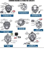
One of these?
ALT Types.jpg
 

Lou C

Supreme Mariner
Joined
Nov 10, 2002
Messages
12,650
That’s how the flappers are, not a perfect fit, if the old ones aren’t melted from a past overheat leave ‘em be. If so change em.
The alternator you have is probably the top left one in the diagram above. Same as mine.
 

Lpgc

Petty Officer 1st Class
Joined
Jun 17, 2023
Messages
258
Thanks @alldodge and @Lou C

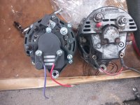
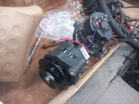
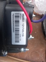
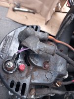
A few pics of my new alternator including a pic of new and old alternators side by side, the new one looks like the one bottom right in the pic above, seems to fit but I won't know for sure until I start to put it all back together.

20240425_122058.jpg

20240425_122205.jpg 20240425_122151.jpg

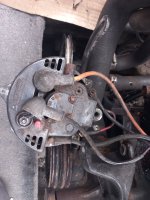
A couple of pics of wiring to the old alternator before I started disconnecting it.

Alternator Wiring 20230709_180748.jpg

Alternator wiring 20230709_180930.jpg

Edit - My old alternator looks like the top left alternator in @alldodge post. Comparing the old and new alternators it seems only the B- connector is in a different position and if I compare to the pic I took of wiring to my old alternator I should be able to work out where all the wires need to go on the new one.

On my boat the ign on and battery voltage sense terminals are wired together, I can see how that works but is it common practice to wire those terminals together? Would it be better to run a separate battery sense wire to the 1/2/both batteries isolator/selector or would the alternator suck power out of the batteries with the ignition turned off?
 
Last edited:

Lpgc

Petty Officer 1st Class
Joined
Jun 17, 2023
Messages
258
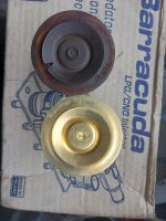
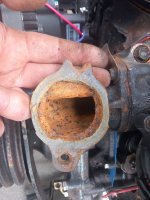
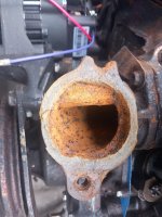
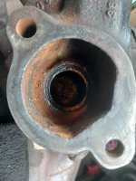
A few pics of old versus new thermostat and the damaged elbow that the thermostat housing sits on.

There's a V cut in the old one. Is this damage or is it supposed to be there to allow some bypass?
20240425_114039.jpg

Broken bolt hole on the elbow but I'm hoping there's still plenty material for a nut fitted underneath to pull on...

20240425_121828.jpg 20240425_121801.jpg

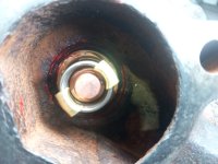
Cleaned up the housing around the area the thermostat sits using a small wire brush in the drill, especially the recessed area the O ring expands outwards into.
20240425_114136.jpg


Fitted the new thermostat and used a bit of Bossil red RTV on the O ring. Watched a Youtube video of someone changing the thermostat, they used RTV on the O ring and under the thermostat but I didn't put any under the 'stat in case it spread out and stuck the thermostat closed.
20240425_120107.jpg

Why do boat engines run at only 71degC when in a car the same engine might run at 85degC? Is it because if they ran hotter and the thermostat opened sudden cold water from the sea could crack the block or is it so they make more power?
 
Last edited:

Lou C

Supreme Mariner
Joined
Nov 10, 2002
Messages
12,650
Prestolite and Mando alternators.jpg
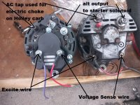
here are the connections on both the OEM Prestolite and the newer style Mando alternators.
If you have a carb with an electric choke it gets powered off the AC tap terminal.
The output B+ is connected with a heavy gauge wire to the B+ terminal on the starter solenoid (same one that the battery cable connects to)
The two bottom ones are the Excite wire and the Sense wire, these both connect to the OMC harness as the original ones were.
 

Lou C

Supreme Mariner
Joined
Nov 10, 2002
Messages
12,650
That part for the thermostat housing, is an adapter that was used on the Ford engines, not used on the GM engines. Sometimes you can find them on a site called NLA Marine
or try Ebay

When replacing OMC thermostats, I always used a coating of OMC gasket sealer (or Permatex Aviation) on the gasket both sides and the bolt threads, as per the shop manual. Never had a leak or a seized bolt doing this, 20 years in salt water.
 

Lou C

Supreme Mariner
Joined
Nov 10, 2002
Messages
12,650
A few pics of old versus new thermostat and the damaged elbow that the thermostat housing sits on.

There's a V cut in the old one. Is this damage or is it supposed to be there to allow some bypass?
View attachment 397219

Broken bolt hole on the elbow but I'm hoping there's still plenty material for a nut fitted underneath to pull on...

View attachment 397223 View attachment 397222

Cleaned up the housing around the area the thermostat sits using a small wire brush in the drill, especially the recessed area the O ring expands outwards into.
View attachment 397220


Fitted the new thermostat and used a bit of Bossil red RTV on the O ring. Watched a Youtube video of someone changing the thermostat, they used RTV on the O ring and under the thermostat but I didn't put any under the 'stat in case it spread out and stuck the thermostat closed.
View attachment 397221

Why do boat engines run at only 71degC when in a car the same engine might run at 85degC? Is it because if they ran hotter and the thermostat opened sudden cold water from the sea could crack the block or is it so they make more power?
2 Reasons:
when water is hotter than approx 160*F, the minerals can precipitate out of suspension and clog the cooling system, especially calcium. This is a bigger problem in salt water or even fresh water with a lot of dissolved minerals.
The other reason is that these open cooling systems (un pressurized) do not put the coolant under pressure like a closed system and while the temp gauge may not indicate overheating, the water can be a good deal hotter in the hottest parts of the cooling system (cyl heads, near exhaust valves) and can actually have localized boiling in those locations. A pressurized cooling system prevents this from happening.
Why are they not standard on inboards? Cost and complexity. However IMHO a closed system is far superior. Better performance because the engine runs at the temp that GM or Ford intended, and much less corrosion.
 

Lpgc

Petty Officer 1st Class
Joined
Jun 17, 2023
Messages
258
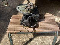
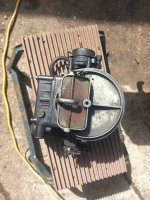
Thanks @Lou C , that helps. Yes it is a Holley 2bbl with electric choke. That explains the AC tap connection (y)

20240425_145856.jpg 20240425_145811.jpg

I might rebuild the carb but wondering if I should leave it alone until I've at least tested the engine in case I mess up mixture settings during the rebuild. I haven't looked into what rebuild kit I'd need yet, that might be another question in future...

Ahh yes I overlooked the boiling point aspect. I would much rather have a pressurised system but does raw water cooled mean you're less likely to break down due to over pressure leading to coolant loss if there's ever an hg issue? Heh, I suppose you're more likely to have a hg problem in the first place with a raw water cooled setup.
 

Lou C

Supreme Mariner
Joined
Nov 10, 2002
Messages
12,650
Thanks @Lou C , that helps. Yes it is a Holley 2bbl with electric choke. That explains the AC tap connection (y)

View attachment 397227 View attachment 397226

Ahh yes I overlooked the boiling point aspect. I would much rather have a pressurised system but does raw water cooled mean you're less likely to break down due to over pressure leading to coolant loss if there's ever an hg issue? Heh, I suppose you're more likely to have a hg problem in the first place with a raw water cooled setup.
Well the raw water cooled system is simpler for sure. Less to go wrong. However, over time what happens especially in brackish or salt water, you get leaks around the head gaskets (corrosion) water in the oil and eventually have to do a top end engine overhaul. I wound up doing this on mine in 2017, but that was also due to an overheat that damaged the head gaskets and cracked the cyl heads.
I don't think a closed cooling system on a boat is any more trouble than a radiator on a car, except for the fact that the raw water side of the HE has to cleaned out periodically.
To me the huge headache of raw water cooling in areas that get real winter, is if you forget to drain the block even one time and it goes below freezing, you are done. It is new engine time. Look at the fiendishly complex drain systems MerCruiser has pushed on their customers because of this problem, for shame. When a proper closed system would be far superior. BTW, those easy drain systems eventually clog up and guess what happens when they don't drain fully? Cracked block!
So if I ever repowered this boat it HAS to have at least a half closed system (half closed is less complex, cools only the engine, the manifolds stay on the raw water side).
No way will I have salt water running through a nice new cast iron engine!
 

Lou C

Supreme Mariner
Joined
Nov 10, 2002
Messages
12,650
OMC Prestolite alternator for Ford.jpg
here's the missing attachment
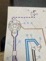
# 60 is the auto choke for the Holley carb

BTW a little OMC trivia that might not apply to yours:
I learned this when I replaced my OEM alt with an ARCO
On some OMC harnesses, there was excessive resistance in the Sense circuit. What can happen then is that the alt gets a low voltage signal and overcharges the battery. The way to tell, is to look at your dash gauge, and then put a multi meter on your battery with the engine running above idle speed. If the readings are close (like 14 V or so) it's OK. But if your dash gauge is reading normal but the batteries are too high like 15+ volts, there's a problem. What ARCO said to do was to run a jumper wire from the B+ terminal to the S terminal. Then tape up the S wire in the OMC harness. This will take battery voltage from the starter solenoid. Another perhaps more accurate way might be to run a wire from the S terminal on the alternator to the common terminal on your battery switch, this will read battery voltage right at the source. Just thought I'd mention it, it was a problem on mine, for sure.
 

Lpgc

Petty Officer 1st Class
Joined
Jun 17, 2023
Messages
258
BTW a little OMC trivia that might not apply to yours:
I learned this when I replaced my OEM alt with an ARCO
On some OMC harnesses, there was excessive resistance in the Sense circuit. What can happen then is that the alt gets a low voltage signal and overcharges the battery. The way to tell, is to look at your dash gauge, and then put a multi meter on your battery with the engine running above idle speed. If the readings are close (like 14 V or so) it's OK. But if your dash gauge is reading normal but the batteries are too high like 15+ volts, there's a problem. What ARCO said to do was to run a jumper wire from the B+ terminal to the S terminal. Then tape up the S wire in the OMC harness. This will take battery voltage from the starter solenoid. Another perhaps more accurate way might be to run a wire from the S terminal on the alternator to the common terminal on your battery switch, this will read battery voltage right at the source. Just thought I'd mention it, it was a problem on mine, for sure.

Thanks, I don't know how the dashboard is wired up but it occurred to me that if the ign on wire connects to the ign switch at the front of the boat (as opposed to coming from a relay at the rear), then if the ignition switch gets power from the same wire that runs to the front to power other stuff like lights etc any voltage drop on that wire would result in the batteries getting too much charge... Hence my question about running a separate wire from Vsens on the alt direct to the battery isolator switch.

S terminal being the unswitched starter terminal?
 

Lpgc

Petty Officer 1st Class
Joined
Jun 17, 2023
Messages
258
Well the raw water cooled system is simpler for sure. Less to go wrong. However, over time what happens especially in brackish or salt water, you get leaks around the head gaskets (corrosion) water in the oil and eventually have to do a top end engine overhaul. I wound up doing this on mine in 2017, but that was also due to an overheat that damaged the head gaskets and cracked the cyl heads.
I don't think a closed cooling system on a boat is any more trouble than a radiator on a car, except for the fact that the raw water side of the HE has to cleaned out periodically.
To me the huge headache of raw water cooling in areas that get real winter, is if you forget to drain the block even one time and it goes below freezing, you are done. It is new engine time. Look at the fiendishly complex drain systems MerCruiser has pushed on their customers because of this problem, for shame. When a proper closed system would be far superior. BTW, those easy drain systems eventually clog up and guess what happens when they don't drain fully? Cracked block!
So if I ever repowered this boat it HAS to have at least a half closed system (half closed is less complex, cools only the engine, the manifolds stay on the raw water side).
No way will I have salt water running through a nice new cast iron engine!
When I knew first found out my engine needed a rebuild then read about OMC Cobra parts being difficult to source I thought about the feesibility of converting my setup to a half closed system, that way I could just fit a truck engine and not need to worry about marine cooling system components other than the exhaust manifolds which I soon found out I could still easily buy.
 
Top