1988 50 hp force no spark?

blue fin bass dominator

Seaman Apprentice
Joined
Apr 8, 2024
Messages
38
Do a troubleshooting for the ignition system. Outboardignitiondotcom has the troubleshoot chart. According to the model number from the id tag the engine do not have the Prestolite system with one CDI box with two output channels. It has the one with CDI and ignition coil built in in the same unit.
I have searched eBay and all other sites I could find. Would anyone have any suggestions on where I could find a stator for my 1988, 50hp, US Marine Force engine? Model number 507Y8C. I've had nothing but trouble finding parts for this engine and frustrated is mildly putting it. My stator is a four wire, 2-blue wires and 2-green wires. I have found hundreds of stators and not a single one that fits mine. Any help that anyone can give me would be greatly appreciated!
 

Nordin

Commander
Joined
Jun 12, 2010
Messages
2,555
The stator for your engine should be 300-888793.
Crowley Marine maybe have for 587 dollar, uuuuhhhh!
Outboardignition.com has it for 320 dollar, aftermarket CDI Electronics.
Not cheap either.
 

kalebsheridan

Petty Officer 1st Class
Joined
Aug 14, 2023
Messages
205
I had bought a used CDI stator that had 2 extra wires. Seemed to work fine once I figured out which wires went to what. The extra I just tucked away. The stator I bought was supposed to be for multiple hps., which is why I believe it had extra wires. I have basically the same force as you btw and I had a no spark condition.
 

jerryjerry05

Supreme Mariner
Joined
May 7, 2008
Messages
18,037
The original is a 6 wire. It worked on all the bigger Force's 50 up to 150
The 4 wire is an aftermarket , probably CDI.
The Force motors came with a wiring diagram on the motor(unless someone removed it??) The color code changed and made it confusing.
 

Jiggz

Captain
Joined
Oct 23, 2009
Messages
3,909
So exactly what is wrong with the old stator? Was it burnt? Or could it just be a broken wire that can be repaired with a soldering iron? As mentioned, the original has 6 wires. But take note two yellow wires are twisted together and two blue (brown blue) wires are twisted together and only connects to two terminals. The other two yellow wires connects to the rectifier which is the charging circuit of the stator. Remember the stator serves two functions, first as power source for the ignition system and second, as a charging unit for the battery.

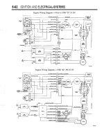
There are many stator on ebay that fits your 50 HP motor. But most of them only has 4 wires, i.e. green, white and 2 yellows. The yellow wires goes to the rectifier while the green and white goes to the terminal for the module or power pack. Others have 6 wires with two blue and two red and two yellows. Again, with this wiring configuration, the two reds connect together to one terminal of the power pack module and the two blue does the same. The two yellow still connects to the rectifier. You can also just connect one red and one blue to the power pack module and just tape off the remaining blue and red wires. In fact, if you put an ohmmeter between the two red wires you'll get zero ohms as these two wires are connected together internally and the same is true with the two blue wires. Here's the wiring diagram for your "D"Force 1988 Prior to D 50 HP wiring diagram.jpg50 HP. If you have the Green, Green and Blue, Blue stator then your motor must be a 1987 or 1988 50HP prior to the "D" wiring. Anyways, the four wire stator or 6 wire stator will still work as explained above. Remember the two yellow wires connects to the rectifier.
 

blue fin bass dominator

Seaman Apprentice
Joined
Apr 8, 2024
Messages
38
my model number is 507Y8C. I have the 1988 C model not the D that came after. Great intel on the wires being connected together internally. I appreciate you guys helping me out. I do my own mechanic work on my classics and Harleys but this boat has been a little more challenging.
 

blue fin bass dominator

Seaman Apprentice
Joined
Apr 8, 2024
Messages
38
also in response to your question, I lost spark on both cylinders. as per the service manual, I tested the voltage and came up way short on what the output was supposed to be. I forget exactly what that voltage was off the top of my head.
 

Jiggz

Captain
Joined
Oct 23, 2009
Messages
3,909
Sometimes, lost of total sparks on all cylinders could be as simple as the safety lanyard being activated. This is a lanyard that is supposed to be worn by the driver and if he happened to be thrown overboard will activate the shut down switch, hence stopping the motor. Disconnecting the black/yellow or white wire from the terminal board inside the engine cowling will by-pass the shut/stop switch. If sparks return after disconnecting this wire, then the safety lanyard switch is activated. If sparks do not return, then the problem is somewhere else.
 

blue fin bass dominator

Seaman Apprentice
Joined
Apr 8, 2024
Messages
38
Ok, I see. When I wired up the new ignition switch, I did not hook up the safety lanyard switch because I am going to have to replace the switch itself. At the time, I was going to come back to that before putting it on the water. I had unhooked it and forgot where to wire it up so I just left it unhooked. What would cause me to have low voltage coming from the stator? Could that cause the low voltage? Reason I ask is because per the service manual, mine was about 30 volts shy of what they said it should be. I ran through all the recommended steps to troubleshoot ignition problems and that is where I stopped. When I took the stator off, I did not see any bad places in the wires and the stator wasn't visibly charred.
 
Last edited:

blue fin bass dominator

Seaman Apprentice
Joined
Apr 8, 2024
Messages
38
I want to say the voltage should be around 130 volts and I only had around 100. Like I said, I forget the exact numbers but I do remember I was about 30 volts short of what they said should be coming from my stator.
 

blue fin bass dominator

Seaman Apprentice
Joined
Apr 8, 2024
Messages
38
Nordin, I do not have the CDI box. I just have the two coils and they are pretty much obsolete. I have not been able to find them either. On the bottom of my stator it says it is a Prestolite stator.
 

blue fin bass dominator

Seaman Apprentice
Joined
Apr 8, 2024
Messages
38
Jiggz, hey I unhooked the stop wire off of the terminal and checked for spark. Both cylinders are still dead. After I tried that today, I remember trying that once before based off of info I found in one of the forums. Thanks for the suggestion though. I'm going to go ahead and find a stator for it. There's a lot of sentimental value in the boat so I will just have to bite the bullet and pay the high price for one from CDI.
 

Nordin

Commander
Joined
Jun 12, 2010
Messages
2,555
Blue fin is the copy of my comment in the top of this thread from another thread from you?
Got confused with your comment in post #11.
However the stator output should be 180VDC DVA or more.
Before buying a new stator check the wires from the stator from crack, bad insulation etc.
Check the resistance for the stator, should be 680-800 Ohm.
Pull the flywheel and check the magnets, it maybe have the glued magnet strip.
Not uncommon the strip is loose.
 

blue fin bass dominator

Seaman Apprentice
Joined
Apr 8, 2024
Messages
38
Blue fin is the copy of my comment in the top of this thread from another thread from you?
Got confused with your comment in post #11.
However the stator output should be 180VDC DVA or more.
Before buying a new stator check the wires from the stator from crack, bad insulation etc.
Check the resistance for the stator, should be 680-800 Ohm.
Pull the flywheel and check the magnets, it maybe have the glued magnet strip.
Not uncommon the strip is loose.
As a matter of fact, when I pulled the flywheel off to inspect the stator and trigger, part of my mag strip came out too. half of it stayed in the flywheel. I just tucked it back in place and reinstalled the flywheel. There shouldn't be any way for it to move since it butts up to the other half on each end. Is this wrong? should I have epoxy glued the magnet to the flywheel rather than just putting it back in? I will get my DVA meter and check voltages again tomorrow and also check the ohms of the stator. Thanks for your help sir!
 

Nordin

Commander
Joined
Jun 12, 2010
Messages
2,555
Yes you have to glue the magnet strip back!
It will move again if you not glue it.
Glue it back with super glue or epoxi glue.
Clean the surface as best you can then a thin coat of glue and put the magnet strip back in the right place.
 

blue fin bass dominator

Seaman Apprentice
Joined
Apr 8, 2024
Messages
38
Yes you have to glue the magnet strip back!
It will move again if you not glue it.
Glue it back with super glue or epoxi glue.
Clean the surface as best you can then a thin coat of glue and put the magnet strip back in the right place.
Ok, I will do that tomorrow!
 

Jiggz

Captain
Joined
Oct 23, 2009
Messages
3,909
Nordin got it all correctly. With the flywheel off check the resistance of the stator charge coil, between wires bl/yel or bl/bl and it should be around 680-800 ohms. If you are getting this resistance reading most likely the stator is still good. Now check continuity of wires from stator to terminal boards to make sure there's not a cut off wire. I use safety pins to punch through insulation from the base of the stator wire to each terminal end to check for continuity.
If you do not get the correct resistance, then it's time to replace the stator. Mind you, make sure you read resistance as close as possible to the base of the stator wire. This is to mitigate any broken/loose wire connection from terminal end to the wire's base.
 

blue fin bass dominator

Seaman Apprentice
Joined
Apr 8, 2024
Messages
38
Nordin got it all correctly. With the flywheel off check the resistance of the stator charge coil, between wires bl/yel or bl/bl and it should be around 680-800 ohms. If you are getting this resistance reading most likely the stator is still good. Now check continuity of wires from stator to terminal boards to make sure there's not a cut off wire. I use safety pins to punch through insulation from the base of the stator wire to each terminal end to check for continuity.
If you do not get the correct resistance, then it's time to replace the stator. Mind you, make sure you read resistance as close as possible to the base of the stator wire. This is to mitigate any broken/loose wire connection from terminal end to the wire's base.
Jiggz, thank you for the intel. I took a pic of your instructions and will follow them to a T once I get the boat pulled back in to my shop. I have never had to test or mess with a stator before in my life so this is a good learning tool for me. You guys have been so helpful and I really appreciate you all taking the time to explain all this to me. I will reply back tonight after I record my findings with the ohm meter. I'm gonna let it cool off just a tad before I do all this. It's hotter than a road lizard here in Oklahoma right now.
 

blue fin bass dominator

Seaman Apprentice
Joined
Apr 8, 2024
Messages
38
Yes you have to glue the magnet strip back!
It will move again if you not glue it.
Glue it back with super glue or epoxi glue.
Clean the surface as best you can then a thin coat of glue and put the magnet strip back in the right place.
I will clean the flywheel and magnet surface area with carb cleaner to get all the residue off of it then wipe it real good again with alcohol to make sure its clean and oil free. Thank you for replying and helping me out. This project means a lot to me. My kids spent a lot of time in this boat with me when they were younger. They are both deceased now so this means a lot to me to see to the end. Thanks again sir!
 

blue fin bass dominator

Seaman Apprentice
Joined
Apr 8, 2024
Messages
38
Nordin got it all correctly. With the flywheel off check the resistance of the stator charge coil, between wires bl/yel or bl/bl and it should be around 680-800 ohms. If you are getting this resistance reading most likely the stator is still good. Now check continuity of wires from stator to terminal boards to make sure there's not a cut off wire. I use safety pins to punch through insulation from the base of the stator wire to each terminal end to check for continuity.
If you do not get the correct resistance, then it's time to replace the stator. Mind you, make sure you read resistance as close as possible to the base of the stator wire. This is to mitigate any broken/loose wire connection from terminal end to the wire's base.
I checked the ohms on everything that had copper on it or to it and the blue/blue wires and the yellow/green wires and everything showed 0 ohms. double checked the meter to make sure I had it calibrated at exactly zero and still o ohms. where I am uncertain at is where are the charge coils? I have 5 without any copper wire wrapped around them, I have 5 that has light colored copper wire wrapped around them and 10 that have a darker colored copper wrapped around them. sorry if this is a dumb question to ask but like I mentioned before, I know nothing about a stator. Never had to work on one. I did remove the flywheel and when I pulled it off the shaft, the strip magnet stayed on the stator. It came completely out of the flywheel this time. It is not a 2 piece magnet, it is one strip cut to fit the I.D. of the flywheel. I got both the flywheel and magnet cleaned up and epoxy glued the strip back in the flywheel. I will reinstall the flywheel tomorrow when the glue has cured and see what happens then.
 
Top