1963 16' Star Dust I believe

StarTed

Senior Chief Petty Officer
Joined
Jul 14, 2015
Messages
694
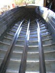
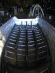
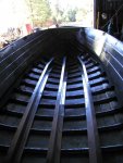
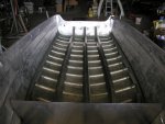
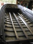
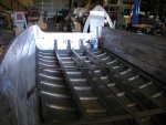
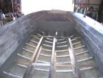
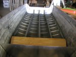
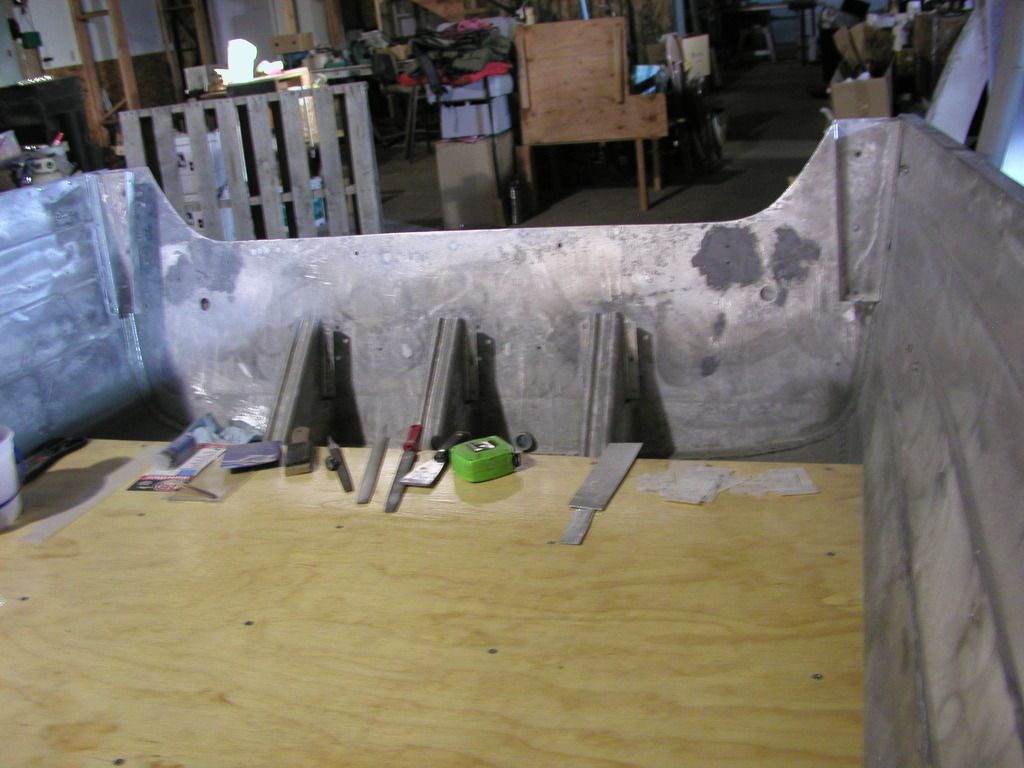
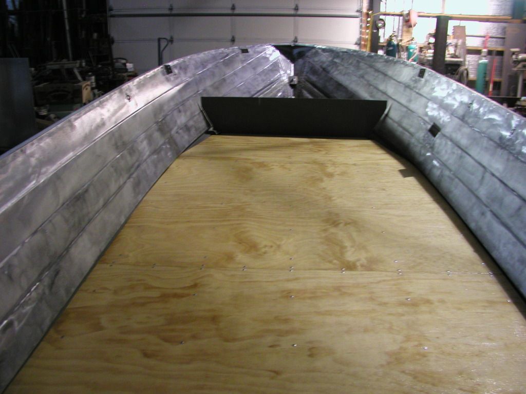
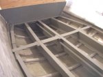
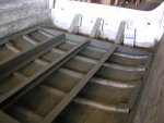
Now I'll go back to show the floor stringers. They were made from 13 gauge aluminum that is the same thickness as the transom aluminum. The shop I had make them sold me a 4X10 sheet that I purchased to add some to the transom to make it a standard shaft. They also stiffened up the bottom so there should be less flexing. We'll see.

fetch

The stringers are installed in this view and the next few.

fetch


fetch


fetch


I sure appreciate all the help I received getting the photo problem solved. The stringers were placed where I wanted them then each end drilled and fastened by Clecos to hold them while I drilled the remaining holes into the ribs. I used a hole duplicator to use existing holes as much as possible. Then I removed the stringer and deburred their holes. That made the installation with 3/16 pop rivets tighter. Each stringer is 10' long, in front of that I plan to make a raised deck.
 

Attachments

  • 2015-08 003 (Small).jpg
    2015-08 003 (Small).jpg
    105.7 KB · Views: 3
  • 2015-08 001 (Small).jpg
    2015-08 001 (Small).jpg
    81.8 KB · Views: 4
  • 2015-08 002 (Small).jpg
    2015-08 002 (Small).jpg
    95.1 KB · Views: 4
  • 2015-08 004 (Small).jpg
    2015-08 004 (Small).jpg
    80.6 KB · Views: 4
Last edited:
StarTed

Senior Chief Petty Officer
Joined
Jul 14, 2015
Messages
694
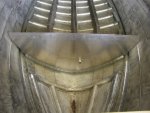
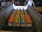
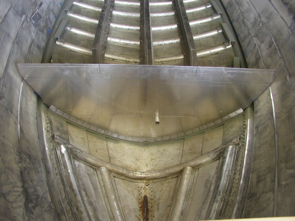
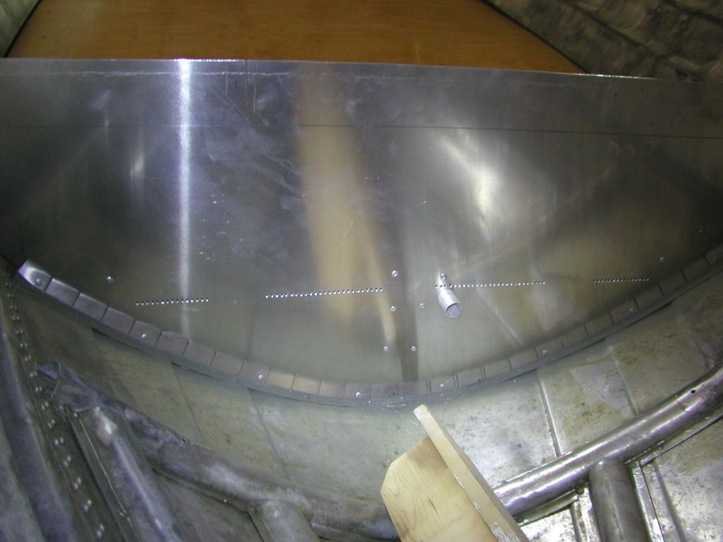
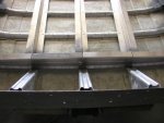
You will notice that angle aluminum was installed at the end of the ribs to keep the floor secure. I plan to make it mouse proof, that is no holes 1/4" or greater. The bulkhead is fastened to the rib with pop rivets It was cut in the general shape but not touching the sides.If you look closely in the next photo you will see a series of 1/8" holes to aid in a little ventilation. The hull will be filled with Dollar Tree noodles. I purchased 52 and could have used another 20 but I found some other closed cell foam lying around.

fetch

There are 2 slits cut down from the top that will be rolled back to form the entrance and an aluminum tube going back under the floor for the front area drainage.

More pictures later.
 

Attachments

  • 2015-08 005 (Small).jpg
    2015-08 005 (Small).jpg
    84.1 KB · Views: 4
Last edited:
StarTed

Senior Chief Petty Officer
Joined
Jul 14, 2015
Messages
694
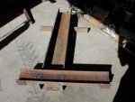
I disabled my touch pad and now I don't seem to keep losing everything as I move along. Maybe this is a good time to comment on the brake I'm building. So far I've managed to scrounge the metal I need. I plan to make a trip to the farm near Royal City to check for hydraulic cylinders and more heavy metal. The brake will be 5' wide in the brake area with open ends to slide along the work if needed. Most of the metal so far is 1/2" thick so it's a struggle for me to lift and pack around. Some of the metal is 1X6 5' long steel, 4 pieces.

fetch

This is one of the legs.

fetch

Here is the other leg.

fetch

Working on the base for the brake's press part.

fetch

A start of the assembly.

I'll be using this to make some long aluminum bends and future work on my 1948 Pontiac.

More on this later.
 

Attachments

  • 2015-10-22 006 (Small).jpg
    2015-10-22 006 (Small).jpg
    73.7 KB · Views: 3
  • 2015-10-22 007 (Small).jpg
    2015-10-22 007 (Small).jpg
    81.7 KB · Views: 3
  • 2015-10-22 008 (Small).jpg
    2015-10-22 008 (Small).jpg
    89.8 KB · Views: 3
  • 2015-10-22 010 (Small).jpg
    2015-10-22 010 (Small).jpg
    97.2 KB · Views: 3
Last edited:
jbcurt00

Moderator
Staff member
Joined
Oct 25, 2011
Messages
25,034
Just in case you missed his posts, Watermann asked a couple questions while you were posting.

Work and brake look good
 
Last edited:
StarTed

Senior Chief Petty Officer
Joined
Jul 14, 2015
Messages
694
Watermann,

Thanks for the input. I think your pictures make a better patch than mine but I've moved on. It I see any future problems with my fix I'll be sure to use your suggested method. Yes, I covered the inside below the waterline with Gluv-It before installing the floor stringers and angle supports for the tloor at the end of the ribs. After the stringers were installed I made end covers to keep out pesky critters along with a 1"aluminum tube for future bow deck drainage. I plan to connect the bow deck with hose (heater hose?) clamped on both ends. There will be a hatch to access the clamps and make the space usable for storage.

fetch

This is the stern cap showing the ventilation holes and the drain tube from the front.

fetch

This picture shows the angle floor supports at the end of the ribs.

fetch

Now I've added plates to support the ends of the plywood.

fetch

Another view in the other direction showing the plywood end supports installed.

When the stringer work was finished I sprayed them and the area with self etching primer.

fetch

Self etching primer sprayed into the area.

fetch

Another view after spraying in self etching primer.

Next comes the floor.
 

Attachments

  • 2015-08 016 (Small).jpg
    2015-08 016 (Small).jpg
    61.3 KB · Views: 3
  • 2015-08 017 (Small).jpg
    2015-08 017 (Small).jpg
    66.9 KB · Views: 3
  • 2015-08 006 (Small).jpg
    2015-08 006 (Small).jpg
    77 KB · Views: 3
  • 2015-08 007 (Small).jpg
    2015-08 007 (Small).jpg
    97.8 KB · Views: 3
  • 2015-08 008 (Small).jpg
    2015-08 008 (Small).jpg
    84.8 KB · Views: 3
  • 2015-08 009 (Small).jpg
    2015-08 009 (Small).jpg
    94.8 KB · Views: 3
Last edited:
oldhaven

Chief Petty Officer
Joined
Aug 30, 2015
Messages
576
Very innovative and creative work. Designing things originally is not as hard as improving on the original design without causing unintended consequences.

Ron
 

StarTed

Senior Chief Petty Officer
Joined
Jul 14, 2015
Messages
694
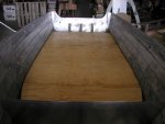
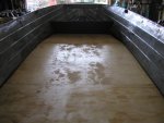
I cut 3 pieces of plywood to fit the boat sides using cardboard templates. Then I sealed them with a couple of coats of epoxy. That made 4 coats on the edges. After they hardened I fit in the 1/2" plywood floor, drilled 2 holes in the front piece and inserted 2 - 3/16" rods and drilled the remaining holes. Then I did the next piece in a similar fashion. The last piece was done the same with the floor coming out right where I expected it to come. I then removed the floor and removed any burs.

fetch

Here is my flotation. used 52 Dollar Tree noodles and could have worked in another 20. I found some other closed cell foam that I used instead.

fetch

The front plywood lying in place. I had the wrong picture so here is another try for the correct one.

fetch

The other pieces were put in place and secured with long 3/16" pop rivets.

fetch

Here is looking forward before putting on another coat of epoxy.

Next is the transom. Months earlier I already laminated 2 sheets of 3/4" marine grade plywood for the transom and cut it for a standard shaft motor. Then I drilled the holes a little large for drainage and needed bolts and put epoxy in them using Q-Tips.
 

Attachments

  • 2015-08 018 (Small).jpg
    2015-08 018 (Small).jpg
    74 KB · Views: 5
  • 2015-08 019 (Small).jpg
    2015-08 019 (Small).jpg
    81.1 KB · Views: 5
  • 2015-08 020 (Small).jpg
    2015-08 020 (Small).jpg
    65.9 KB · Views: 5
  • 2015-08 021 (Small).jpg
    2015-08 021 (Small).jpg
    77.5 KB · Views: 4
Last edited:
Watermann

Starmada Splash of the Year 2014
Joined
Jan 12, 2013
Messages
13,787
Ted if your rib cracks were stop drilled and there wasn't any leaking after sealing then the cracks shouldn't grow out from under your repair. Since the crack has compromised the rivet hole and the rivets ability to swell and seal then 5200 is used to make the repair water tight.

The reason I asked about gluvit was seeing the pic of the bow keel area below I can see the original SC "smeg" but no gluvit in the pit or on the seams. Maybe you're better at putting that stuff on than I've been, as mines ran all over. :lol: The keel seam up front is a chronic leak area for all riveted tin boats because it always takes the brunt of landings. I'm not sure but I think you've caught us up to your progress so far?
2015-08%20005_zpsb9nm3enr.jpg


I just noticed that your SC has the lap design carried from the sides on to a portion of the bottom of the boat, interesting as I haven't seen that before and it doesn't look like there are the common 3 strakes riveted on the bottom.

I really like the extra deck supports you had made up and your right they should had some strength to the hull as well. :thumb:
 

StarTed

Senior Chief Petty Officer
Joined
Jul 14, 2015
Messages
694
Oldhaven,

Thanks for the observations. The stringers went in quite well considering the ribs are probably not exactly the same as when built 52 years ago. Those stringers bent in a Z shape are quite rigid so it took a little tweaking at the bottom to make them tight on all ribs.

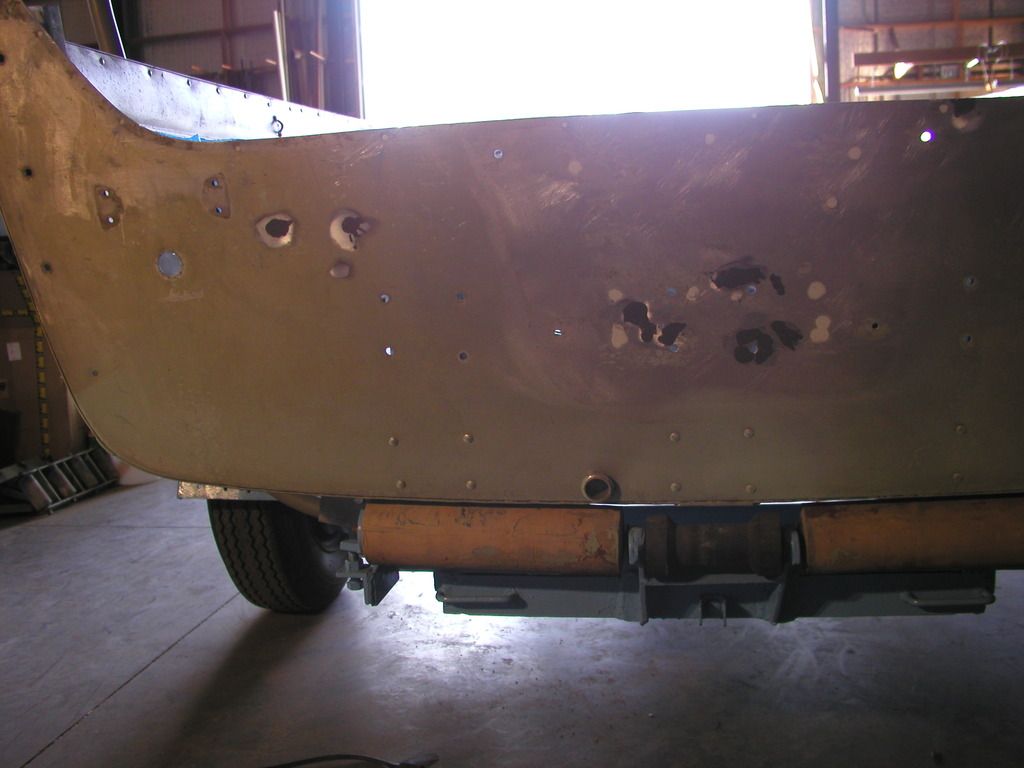
Here is some transom work. I'll have some questions on the transom aluminum later. I still haven't figured out how I should attach the 5" of aluminum that I plan to add on top. That'll come later. Here are more pictures getting us closer to current conditions.


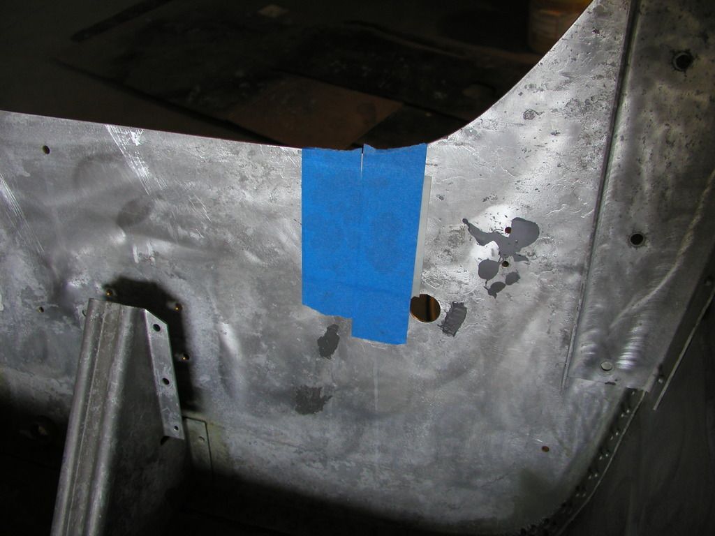
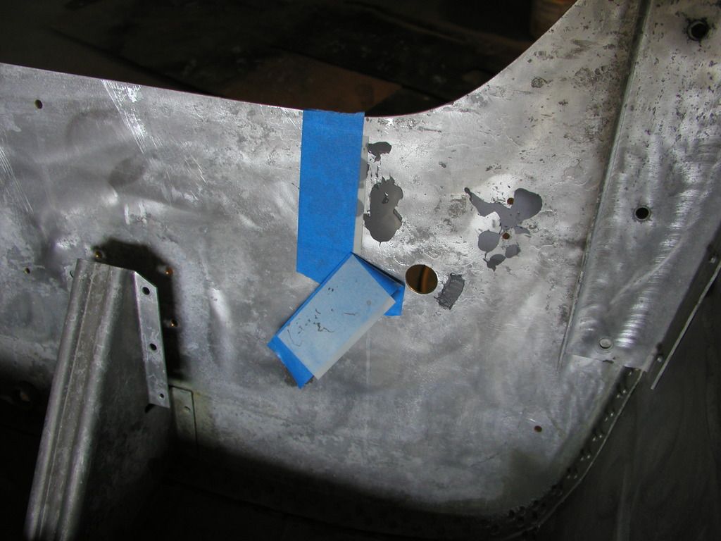
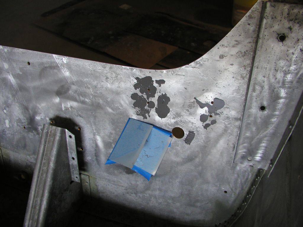
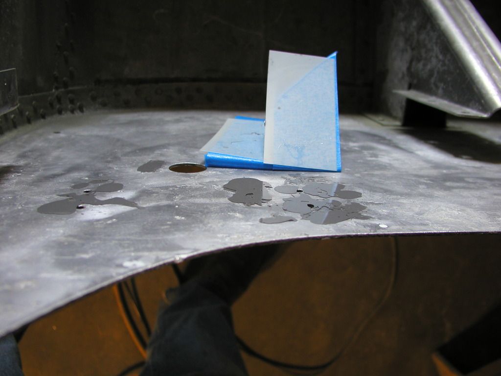
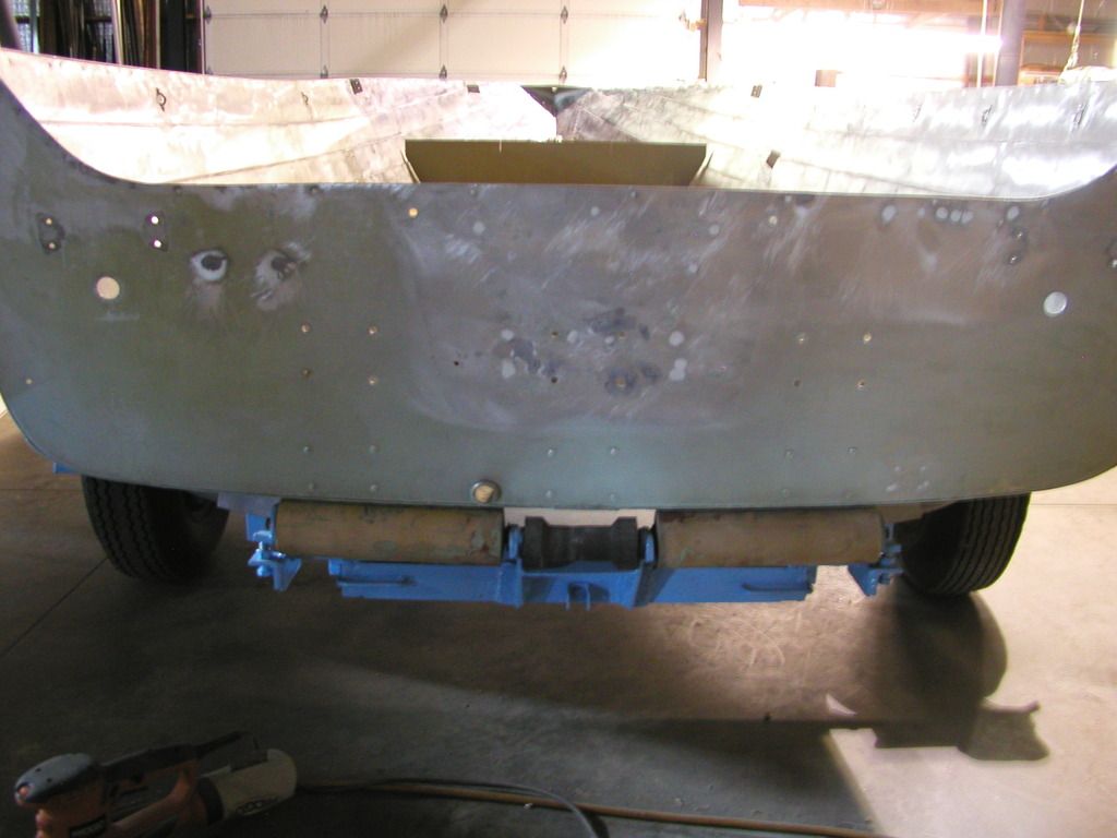
A rear view of the transom. The holes were tapered on both sides with a countersink and filled with JB Water Weld. I hope it will hold up. I cleaned out the pits the best I could and filled them with JB Weld that I held in place using some 2" wide plastic strips held in place with painters tape. That worked very well.


Here is a picture of a JB Weld fill.


A day later it came right off.


The other picec pealed back.


Another view showing the effect of using the plastic to keep the JB Weld from drooping.

I'm almost up to date.
 

StarTed

Senior Chief Petty Officer
Joined
Jul 14, 2015
Messages
694
Watermann,

I'm sorry to say that I didn't do the crack patches quite right but they are done now so I'll keep an eye on them. It didn't sink when I drove it before so I think I'll have time to get back should it start taking on water. This is not my first boat, only the first tin boat I've worked on.

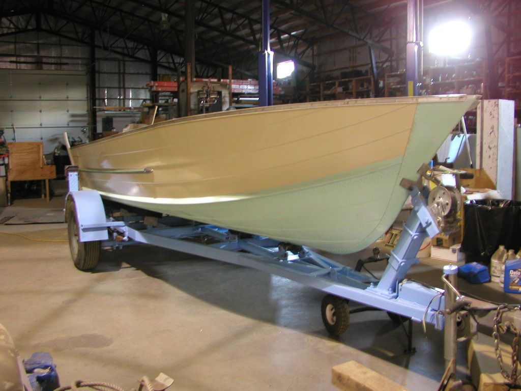
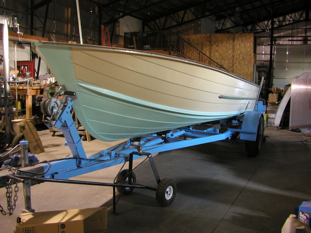
Here are some pictures as it is now.


Starboard side of boat on trailer.


Port side of boat on trailer.


Patched transom.


Outside of patched transom


Floor with another coat of epoxy.

That's the boat to date. I have some other pictures of the trailer roller adjusters that I made.
 

StarTed

Senior Chief Petty Officer
Joined
Jul 14, 2015
Messages
694
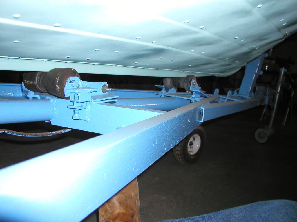
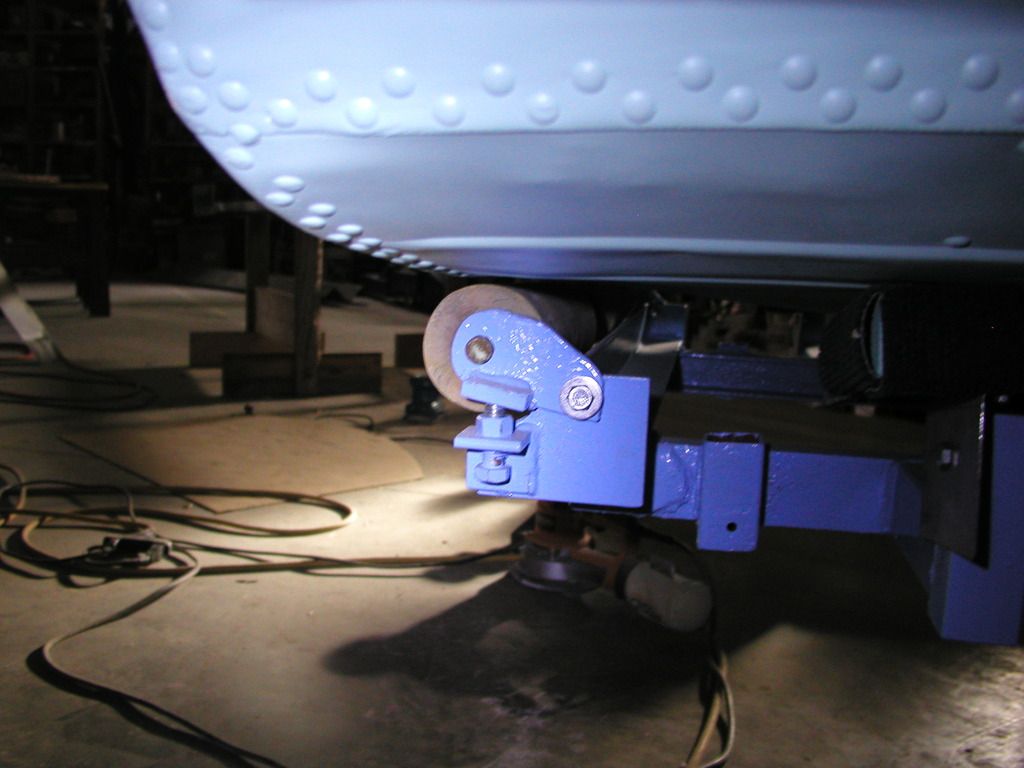
Here are some pictures of the home built trailer that came with the boat. I added center roller adjusters.


Trailer roller adjusters made with 2" angle iron (it's what I had on hand).


Adjuster for the outer end of the transom roller.

I'll throw in another picture showing the bulkhead I installed that better shows the ventilation and drainage tube. I know that the ventilation will be minimal but it should be better than nothing.


Bulkhead aluminum installed to separate the bow area and will be sealed to keep rain water and splashes contained so they'll drain directly to the transom area.

I believe we are now up to date. My next question is how should I attach the 5" aluminum plate (the same thickness) to the top of the existing aluminum transom. I believe welding would be the best option but I do not have enough TIG experience to do that. I need to practice but I'm still not confident. Are there other good options?
 

oldhaven

Chief Petty Officer
Joined
Aug 30, 2015
Messages
576
Great work! I will be borrowing the plastic strips idea when I do my transom. Will you be adding any sheet aluminum on the outside of the transom? That could be sized to hold the extra material filler above the existing transom cut out so there was no gap, and it would reinforce the joint.
 

64osby

Admiral
Joined
Jul 28, 2009
Messages
6,817
With as much damage as your transom skin has, I would look at adding a full skin to the outside.

You could add an aluminum filler for the 5" area so the transom is all one thickness. The new skin could be attached with 5200 and a few rivets
 

g0nef1sshn

Lieutenant
Joined
Feb 24, 2015
Messages
1,291
awesome work! I got a feeling this one is compete and already splashed! these updates are comming fast bringing us along for a nice pic candy ride lol.
 

Watermann

Starmada Splash of the Year 2014
Joined
Jan 12, 2013
Messages
13,787
Nice work on the transom hole patching, it's amazing how tough that JB is. I did some testing with JB and MT on a spare piece of AL before I used it on my boat. I tossed, kicked, stomped and threw that piece of AL all around my driveway and both stayed in the holes. The only way I got it to fail was with a hammer beating on it. You'll be fine as long as you keep people with hammers away from your boat and the repairs to the transom are even backed by ply so no worries. That is why JB or MT should not be used to fill holes on the bottom of the boat as an impact with a rock and the hole could open up.
 

StarTed

Senior Chief Petty Officer
Joined
Jul 14, 2015
Messages
694
I like your suggestions oldhaven and 64soby. I have plenty of 14 gauge aluminum to work with (still over 3 sheets 4X10). Do you think 14 gauge will be stiff enough? I may have enough 13 gauge aluminum left over that is the same thickness as the existing transom skin. I may be able to get another sheet for 50 bucks but I'm not sure I need that much aluminum lying around. I also have part of a sheet of diamond plate aluminum at the farm. I plan to make a trip there on Monday with my oldest son to scrounge for hydraulic cylinders and will be bringing it back along with whatever else I think I can use on the brake.
 

StarTed

Senior Chief Petty Officer
Joined
Jul 14, 2015
Messages
694
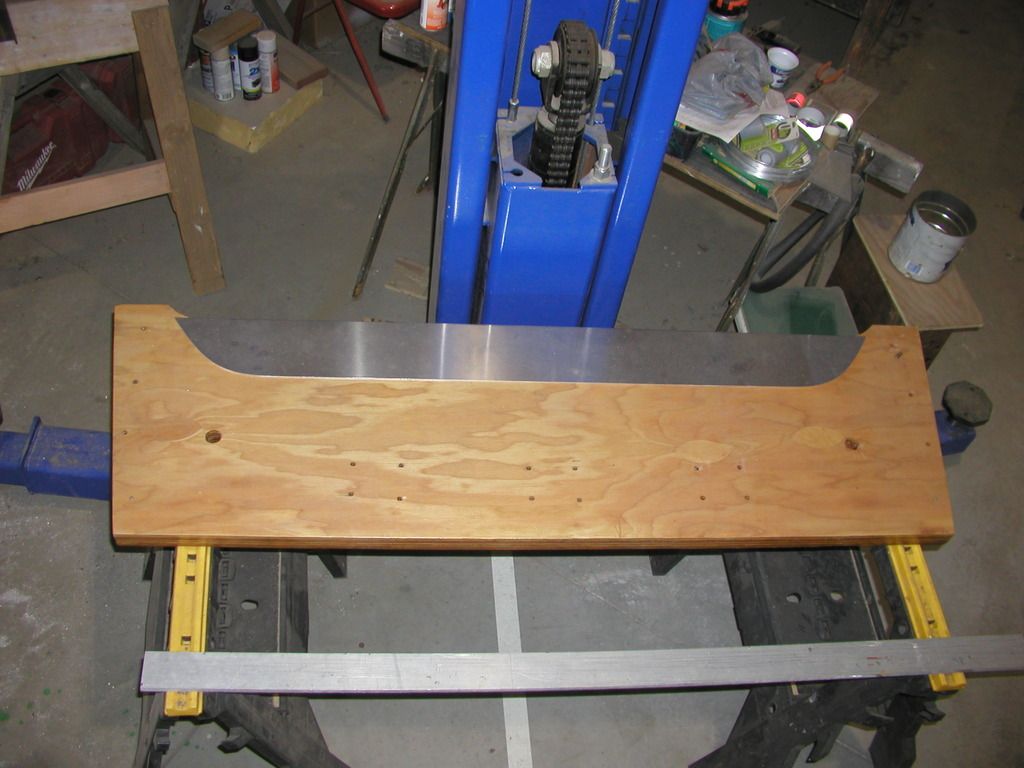
Here is a picture of the aluminum filler I made to fit above the existing transom aluminum. It is lying on the new transom board.


New transom with aluminum filler I made that needs to be attached some way.

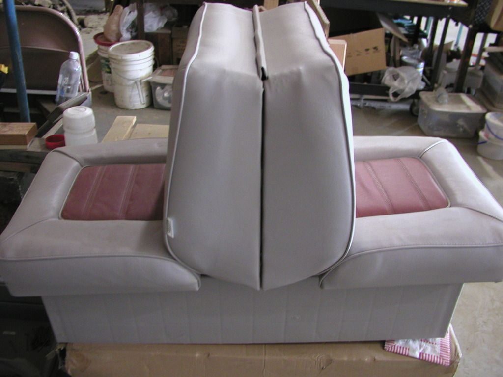
Here is one of the seats I have to use.


New seat setting on box with other seat.

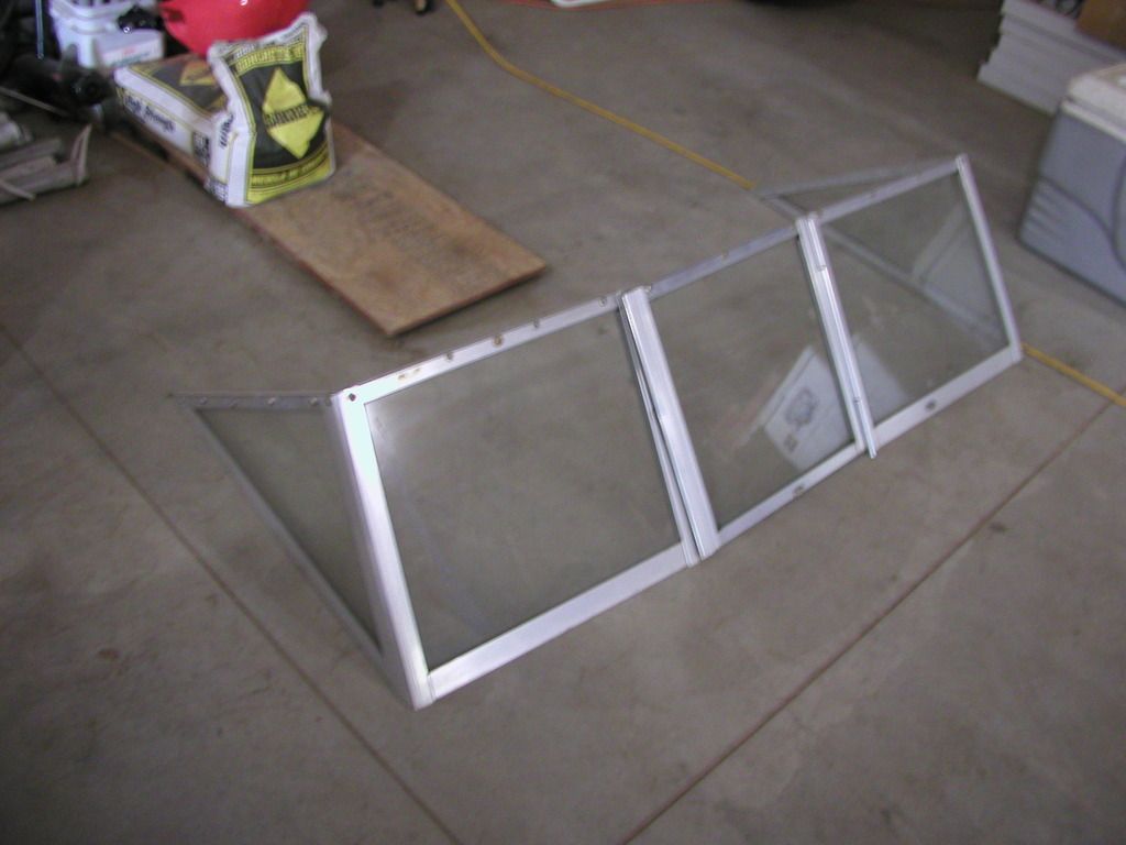
Here is the used windshield I plan to mount on aluminum consoles that I still need to design and make.


Used windshield with pass through center.

The transom is my next boat work. You can see that I'll have plenty of bending to do on my new brake once I get it built. There should be a pump, control valve, hydraulic fluid tank and maybe some line lying around here somewhere or else I can find some at the farm.
 

StarTed

Senior Chief Petty Officer
Joined
Jul 14, 2015
Messages
694
Thanks for the input Watermann. I still may add a second skin to the back if I can feel sure that water won't work its way in between.
 

oldhaven

Chief Petty Officer
Joined
Aug 30, 2015
Messages
576
I like your suggestions oldhaven and 64soby. I have plenty of 14 gauge aluminum to work with (still over 3 sheets 4X10). Do you think 14 gauge will be stiff enough? I may have enough 13 gauge aluminum left over that is the same thickness as the existing transom skin. I may be able to get another sheet for 50 bucks but I'm not sure I need that much aluminum lying around. I also have part of a sheet of diamond plate aluminum at the farm. I plan to make a trip there on Monday with my oldest son to scrounge for hydraulic cylinders and will be bringing it back along with whatever else I think I can use on the brake.

I was going to do something similar on my project and make a raised area for mounting a long shaft auxiliary motor, but have changed my plans. Due to the corrosion on my transom I will be adding at least a 3/16th inch sheet of aluminum on the outer transom skin, covering about 4 feet of the transom. I will not be changing the original profile. I have been advised to make sure that there are no voids between the transom skin and this new plate so no water can collect or be drawn in by capillary action and cause more damage, so it will have to be carefully done. My opinion, FWIW, is that 13 or14 ga would probably be fine since you have a pretty solid one piece wood transom there and the skin is more of a water barrier than for strength, but it wouldn't hurt to make it a bit more rigid by going thicker.
 
Top