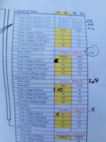
Yamaha 200ETXN 1984 Stator Values

Jprevat

Petty Officer 1st Class
Joined
Apr 25, 2016
Messages
321
Hey yall,
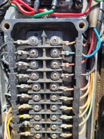
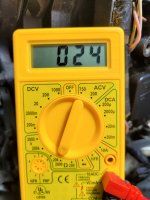
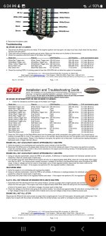
I am having a problem with no fire on my top two cylinders on the port side of the engine. I tested the ohms using the CDI website for reference. Everything checks out as it should except for the ohms between the red/black stator wire and the blue. CDI says that oem should read between 65 and 130 ohms, but I am seeing 24. I ordered a used stator from Strouds Marine to see if I could have an easy fix but it tests exactly the same at 24 ohms.
Am I missing something or did I receive a bad stator that is messed up in the exact same way my current one is?
If anyone can verify these oem values I would be extremely grateful.
 

Attachments

  • 20230507_113016.jpg
    20230507_113016.jpg
    2.1 MB · Views: 4
  • 20230507_113052.jpg
    20230507_113052.jpg
    1.2 MB · Views: 4
  • Screenshot_20230505_183456_Microsoft 365 (Office).jpg
    Screenshot_20230505_183456_Microsoft 365 (Office).jpg
    980 KB · Views: 4

boscoe99

Lieutenant Commander
Joined
Aug 22, 2013
Messages
1,965
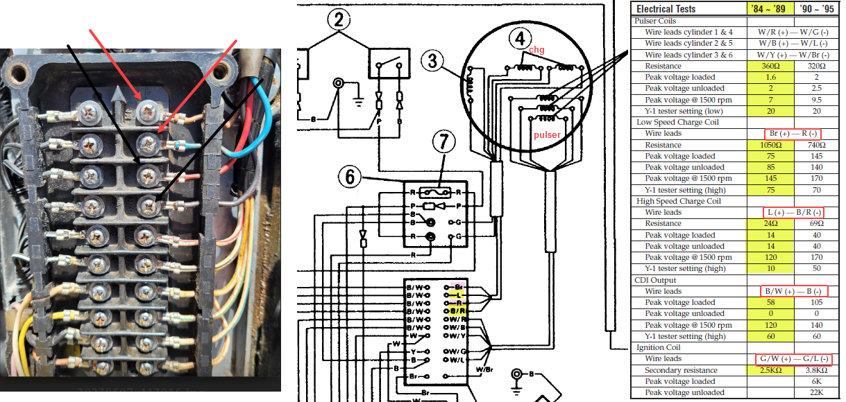
When you say red/black wire do you mean the black/red wire? The wire from the high speed charge coil?

If so, the ohm specification is 24. But more importantly than the wire resistance is the output from the charge coil. What voltages are you seeing?

What are you seeing for the low speed charge coil?
 
Last edited:

Jprevat

Petty Officer 1st Class
Joined
Apr 25, 2016
Messages
321
Yes sir. I did mean the black wire with red tracer. I don't mean to sound like such a novice but when you are asking voltage output do you mean the voltage at the battery while at idle?
 

boscoe99

Lieutenant Commander
Joined
Aug 22, 2013
Messages
1,965
Yes sir. I did mean the black wire with red tracer. I don't mean to sound like such a novice but when you are asking voltage output do you mean the voltage at the battery while at idle?
It is OK not to know something. No one knows it all.

When I mention voltage I am referring to the voltage that is induced within the charge coils. Voltage that is fed to the CDI box.

Tested once with the wires not connected to the CDI box (what Yamaha calls unloaded) and once again with the wires connected to the CDI box (what Yamaha calls loaded).
 

boscoe99

Lieutenant Commander
Joined
Aug 22, 2013
Messages
1,965
Hope I don't sound condescending but a flywheel magnet wizzing by the charge coils creates voltage and sends current to a capacitor within the CDI box. When a magnet wizzes by a pulser coil, the electrical power within the capacitor is discharged to the ignition coil. That then causes the spark plug to fire.
 

Jprevat

Petty Officer 1st Class
Joined
Apr 25, 2016
Messages
321
No problem at all. Any and all information is welcome. Two stroke engine electrical systems are definitely not a second language to me.

To measure said low speed voltage coming to the cdi at which lead while running what lead do i probe?

Thank you for the help and understanding
 
Last edited:

99yam40

Fleet Admiral
Joined
Sep 7, 2008
Messages
9,085
also when you read the stuff on testing I am sure it mentioned peak voltages, read with a special meter for these systems,
or a regular meter with a DVA adapter so you can compare to the minimum specs
 

Jprevat

Petty Officer 1st Class
Joined
Apr 25, 2016
Messages
321
also when you read the stuff on testing I am sure it mentioned peak voltages, read with a special meter for these systems,
or a regular meter with a DVA adapter so you can compare to the minimum specs
I have a dva meter on the way so hopefully I can figure out what's causing the no spark condition.
 

boscoe99

Lieutenant Commander
Joined
Aug 22, 2013
Messages
1,965
You don't really need a peak voltage reading meter. Measure standard AC voltage and then just multiply that number by 1.414.
 

boscoe99

Lieutenant Commander
Joined
Aug 22, 2013
Messages
1,965
No problem at all. Any and all information is welcome. Two stroke engine electrical systems are definitely not a second language to me.

To measure said low speed voltage coming to the cdi at which lead while running what lead do i probe?

Thank you for the help and understanding
Does this make sense to you?
 

boscoe99

Lieutenant Commander
Joined
Aug 22, 2013
Messages
1,965
Would not hurt a thing to remove the connectors one at a time and make sure they are electrically clean and secure.
 

Jprevat

Petty Officer 1st Class
Joined
Apr 25, 2016
Messages
321
Thank you boscoe. That does make sense at least 85% or so. I'll have to pull it all up on a larger screen so I can see it all at once but that is exactly the information I needed.

I'll clean all the connections while I'm at it and let yall know what I find.
 

Jprevat

Petty Officer 1st Class
Joined
Apr 25, 2016
Messages
321
Quick Question: I went through and tested all resistance values and everything tested within a percent of where they were supposed to. Except the G/W and G/L wires for the secondary resistance. When I first touch the leads I see about 430 ish, not the 2.5k spec, but it quickly falls off to zero over the course of a 3 seconds.

I plan on testing all the output voltages Friday when Ill be home watching my little girl. So I will post the results from that as soon as I have them.

I know yall could handle this with your eyes closed but I really appreciate all the help and advice.
 

boscoe99

Lieutenant Commander
Joined
Aug 22, 2013
Messages
1,965
Quick Question: I went through and tested all resistance values and everything tested within a percent of where they were supposed to. Except the G/W and G/L wires for the secondary resistance. When I first touch the leads I see about 430 ish, not the 2.5k spec, but it quickly falls off to zero over the course of a 3 seconds.

I plan on testing all the output voltages Friday when Ill be home watching my little girl. So I will post the results from that as soon as I have them.

I know yall could handle this with your eyes closed but I really appreciate all the help and advice.
On which ignition coils?
 

Jprevat

Petty Officer 1st Class
Joined
Apr 25, 2016
Messages
321
I was trying to measure ohms between the two green wires running from the stator to the smaller distribution block above the cdi with the engine off.

On the spec sheet above it's the last highlighted value in yellow.
 

boscoe99

Lieutenant Commander
Joined
Aug 22, 2013
Messages
1,965
I was trying to measure ohms between the two green wires running from the stator to the smaller distribution block above the cdi with the engine off.

On the spec sheet above it's the last highlighted value in yellow.
The two green wires are from the lighting coil to the rectifer/regulator. Nothing whatsoever to do with the ignition coils. Or the ignition system.
 

boscoe99

Lieutenant Commander
Joined
Aug 22, 2013
Messages
1,965
As Yam notes, that test is for the ignition coils. All six of them.

Are you familiar with ignition coils? Where they are and how they work?


Jprevat

Petty Officer 1st Class
Joined
Apr 25, 2016
Messages
321
Yessir I am familiar. I can't believe I missed that. I was just reading that and assumed it referred to the charge coil of the stator. Guess that's what I get for assuming.

I went ahead and replaced the coils to see if that was going to be an easy fix but saw no change.
 
Last edited:

Jprevat

Petty Officer 1st Class
Joined
Apr 25, 2016
Messages
321
So these are the measured values with a cheap voltmeter with no DVA.

I circled the measurement where I found a null value but I'm not sure what that means as far as which part is faulty. 20230512_161209.jpg
 
Top