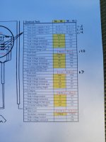
Yamaha 200ETXN 1984 Stator Values

Jprevat

Petty Officer 1st Class
Joined
Apr 25, 2016
Messages
321
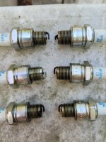
Well those were all DC so these are my AC readings. I pulled the plugs to do a compression test and all cylinders are between 110 and 118 but cylinder 4 (second down port side) looks like it has never fired but was wet.
 

Attachments

  • 20230512_174145.jpg
    20230512_174145.jpg
    1.3 MB · Views: 7
  • 20230512_170825.jpg
    20230512_170825.jpg
    1.7 MB · Views: 7

boscoe99

Lieutenant Commander
Joined
Aug 22, 2013
Messages
1,968
I have no idea what I am seeing.

Let's start over.

Disconnect the brown wire terminal and the red wire terminal from the CDI box. Attach your volt meter to the terminals. One probe to the brown wire terminal and the other probe to the red wire terminal. Voltmeter set on AC. Pull the kill switch lanyard so that the motor won't start. Crank the motor for 5 seconds while watching the volt meter. What is the voltage that you see?
 

boscoe99

Lieutenant Commander
Joined
Aug 22, 2013
Messages
1,968
Well those were all DC so these are my AC readings. I pulled the plugs to do a compression test and all cylinders are between 110 and 118 but cylinder 4 (second down port side) looks like it has never fired but was wet.
Why would you set the meter on DC when you are measuring for AC voltage?
 

Jprevat

Petty Officer 1st Class
Joined
Apr 25, 2016
Messages
321
I have no idea what I am seeing.

Let's start over.

Disconnect the brown wire terminal and the red wire terminal from the CDI box. Attach your volt meter to the terminals. One probe to the brown wire terminal and the other probe to the red wire terminal. Voltmeter set on AC. Pull the kill switch lanyard so that the motor won't start. Crank the motor for 5 seconds while watching the volt meter. What is the voltage that you see?
Yep I definitely had the wrong approach. I'll answer back when I get back on it this weekend.
 

Jprevat

Petty Officer 1st Class
Joined
Apr 25, 2016
Messages
321
Why would you set the meter on DC when you are measuring for AC voltage?
It wasn't on purpose. I ran outside while my newborn daughter was napping and ran the wrong setting in a rush.
 

Jprevat

Petty Officer 1st Class
Joined
Apr 25, 2016
Messages
321
Ok so with the red and brown leads unhooked from the cdi and voltmeter set to 200v AC I saw a max reading of 2.5v
 

boscoe99

Lieutenant Commander
Joined
Aug 22, 2013
Messages
1,968
Ok so with the red and brown leads unhooked from the cdi and voltmeter set to 200v AC I saw a max reading of 2.5v
And did you check both wires to verify that neither is unintentionally shorted to ground?
 

Jprevat

Petty Officer 1st Class
Joined
Apr 25, 2016
Messages
321
And did you check both wires to verify that neither is unintentionally shorted to ground?
The leads where voltage was measured were completely separated and wrapped to be sure. As far as I could chase the wires up the flywheel didn't look damaged either.
 

boscoe99

Lieutenant Commander
Joined
Aug 22, 2013
Messages
1,968
Set the multimeter on the continuity setting. Connect a probe to the brown wire. Connect the other probe to the block. There should no continuity.
 

Jprevat

Petty Officer 1st Class
Joined
Apr 25, 2016
Messages
321
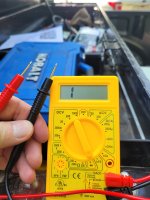
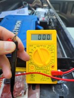
I thought the meters showed an OL when there was no continuity.
at least mine do that.
a 1 would mean 1 ohms of resistance ( not good)
Mine reads 1 with no connection. If I touch the probes
I thought the meters showed an OL when there was no continuity.
at least mine do that.
a 1 would mean 1 ohms of resistance ( not good)
I see a 1 one the left side with no continuity and three digits on the right when there is.
 

Attachments

  • 20230513_171349.jpg
    20230513_171349.jpg
    1.1 MB · Views: 3
  • 20230513_171407.jpg
    20230513_171407.jpg
    1.2 MB · Views: 3

Jprevat

Petty Officer 1st Class
Joined
Apr 25, 2016
Messages
321
With the dva hooked up to the brown and red leads I saw 6.8v with the meter set to AC 200v.
 

99yam40

Fleet Admiral
Joined
Sep 7, 2008
Messages
9,086
did the DVA come with instructions on what to set the meter to, to get the readings?
I thought it was to DCV.

but it sure looks like you low speed charge coil is not putting out what is should be
 

Jprevat

Petty Officer 1st Class
Joined
Apr 25, 2016
Messages
321
did the DVA come with instructions on what to set the meter to, to get the readings?
I thought it was to DCV.
There weren't any in the box and this wasn't the cheapest one by far. I'll find some directions and post back.
 

99yam40

Fleet Admiral
Joined
Sep 7, 2008
Messages
9,086
also looking at your pics it looks to me that you have the meter set to diode testing not ohms settings when doing continuity testing
 

Jprevat

Petty Officer 1st Class
Joined
Apr 25, 2016
Messages
321
did the DVA come with instructions on what to set the meter to, to get the readings?
I thought it was to DCV.

but it sure looks like you low speed charge coil is not putting out what is should be
When set to DCV I am seeing 3.06v
 

99yam40

Fleet Admiral
Joined
Sep 7, 2008
Messages
9,086
was that with you spinning the motor over with the starter?
 
Last edited:
Top