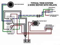
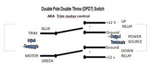
That motor should have a 2 wire PTT motor. Relays provide ground to the motor (up relay to blue wire on PTT motor, down relay to green wire), when not energized. When energized, relays provide power to their respective wires. Since only one relay is energized at a time, either up or down circuit is completed.
Check for +12VDC on green PTT motor lead, when trim activated in the down direction. If no power, suspect corrosion or bad relay.

And I do hear a click when trying to lower motorView attachment 351201
OK so blue wire has 12 V when raising motor
Green wire has no power when trying to lower motor
fuse and little white box (30 amp ) is good also 60 amp fuse is good