Trim

Westeric

Cadet
Joined
Oct 9, 2021
Messages
9
03 Johnson 90 4stroke Motor will trim up but not down I do hear relay clicking when trying to lower
 

Chris1956

Supreme Mariner
Joined
Mar 25, 2004
Messages
27,847
That motor should have a 2 wire PTT motor. Relays provide ground to the motor (up relay to blue wire on PTT motor, down relay to green wire), when not energized. When energized, relays provide power to their respective wires. Since only one relay is energized at a time, either up or down circuit is completed.
Check for +12VDC on green PTT motor lead, when trim activated in the down direction. If no power, suspect corrosion or bad relay.
 

Crosbyman

Vice Admiral
Joined
Nov 5, 2006
Messages
5,440
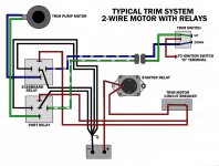
maybe this can help basic 2 wire ptt


the relays simply forward or reverse the current to the trim relay.

if motor works one way seems logical it should work the other way (wires to the motor being ok )

and the big IF is ..... are relays applying juice to the motor in the DOWN mode ?? test with a volt meter

have you tried switching the relays
 

Attachments

  • 2-wire-Trim.jpg
    2-wire-Trim.jpg
    99.9 KB · Views: 5

Westeric

Cadet
Joined
Oct 9, 2021
Messages
9
That motor should have a 2 wire PTT motor. Relays provide ground to the motor (up relay to blue wire on PTT motor, down relay to green wire), when not energized. When energized, relays provide power to their respective wires. Since only one relay is energized at a time, either up or down circuit is completed.
Check for +12VDC on green PTT motor lead, when trim activated in the down direction. If no power, suspect corrosion or bad relay.
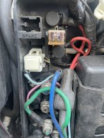
F671EF14-530A-424F-97F7-988086AB8B29.jpeg
OK so blue wire has 12 V when raising motor
Green wire has no power when trying to lower motor
fuse and little white box (30 amp ) is good also 60 amp fuse is good
 

ebbtide176

Commander
Joined
Jan 22, 2002
Messages
2,289
since no one has replied in 30mins, i'll reply. so if the green should have 12v and u already verified 12v on the blue - apparently your meter is working (1st ck) lol
suspect = green wire! if you don't know exactly where it goes (and i aint done auto/marine wiring in 25yrs as a job), i'd go look at the trim switch, capese (ok)? dunno how hard it is to look at those wires on anyone else's boat my mine... but seems logical that you might just have a contact issue with the actual button/switch that should be putting the 12v to the green wire, right? contact cleaner/ burned contact, that kind of thing. but again, i aint no new-fangled boat mech
just my 2c
 

ebbtide176

Commander
Joined
Jan 22, 2002
Messages
2,289
well actually i'd say you would be quicker to just jump batt to the post where the green wire was at (i'd probably pull it off 1st). but so many things are electrically sensitive today, not sure if that might be wrong. since everyone doesn't carry a jumper wire in their shirt pocket (me neither), you could use a piece of solder wire, if you have that. or wire from some old extension cord, heck u can strip it with your teeth and twist it on the 1/4", 5mm bare ends to get a pulse... just not sure about doing the jump with the green wire still attchd. hope that helps.
 

ebbtide176

Commander
Joined
Jan 22, 2002
Messages
2,289
well since either i'm not refreshing this pg enough, or i'm really the only one replying (haven't posted much here in yrs), my posts were piecemeal - meaning; i saw the pic, looks like alot of things today - tough to just swap relays. so, IF the batt V (12v) doesn't fire up the dwn trim, then u narrowed it down to the relay. well for quick troubleshooting - it could still be in the other wire. but that's just what i'd probably do. swapping relays would help but its looks painful.
 

ebbtide176

Commander
Joined
Jan 22, 2002
Messages
2,289
oh, the trim up should be used 1st, so there is range. as in if the motor is down while testing the down trim, it probably has a limit switch to prevent it from even being tested. i'm both old & slo
 

ebbtide176

Commander
Joined
Jan 22, 2002
Messages
2,289
my 2c = click comes from a relay. time to actually swap the relays. then you can pretty much say "hey this works in up and now in down. this other does not" boom
 

ebbtide176

Commander
Joined
Jan 22, 2002
Messages
2,289
oh - swap means either physically or electrically, capese? swap locations OR you may be able to just swap the connections... and with jumper wires if possible. not sure from the pic
 

ebbtide176

Commander
Joined
Jan 22, 2002
Messages
2,289
oh! now not sure about today, but old hardcore relays (for higher current) could be reseated. now I dunno what someone might want to call this whole scenario, but as in old gm solenoids (very much like that relay looks) the big post is a bolt with a square head. so that is on the inside right? it gets a flat spot down inside, and you loosen the top nut, drop down, see if it spins in a square arrangement (hope that makes sense). you pull it back up on a different "ledge/square" and tighten the nut. that was the way they used to make high current relays/solenoids anyway.
 

Crosbyman

Vice Admiral
Joined
Nov 5, 2006
Messages
5,440
green and blue motor works both ways so Voltage/current must be presented in alternate directions ..up or down

since the motor can trim UP ok then both wires from the relays are ok and do pass juice to the motor because one wire has 12v and the other is grounded.


In the reverse order DOWN no power appears on the GREEN wire presumably tested between the green wire and engine body. By the way while you test for 12v also test the other wire (blue) for it's ground since the motor needs both ground and 12v from the relay .


if the green can carry the necessary ground for the UP operation the wire is physically good and the relay isn't doing it's job of flipping Green to +12v .

option 1- relay contacts defective swap relays if good buy a relay
option 2- + 12v is not reaching the upper contact of the bottom relay in the above picture .... find the +12v
 

Crosbyman

Vice Admiral
Joined
Nov 5, 2006
Messages
5,440
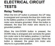
or better said by the ETEC FOLKS.....
 

Attachments

  • ETEC TRIM TESTING.JPG
    ETEC TRIM TESTING.JPG
    55.6 KB · Views: 1

Crosbyman

Vice Admiral
Joined
Nov 5, 2006
Messages
5,440
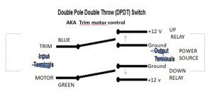
see pict.

in the non operating mode both blue and green are grounded with either wire waiting for the other to flip to +12V thus reversing current flow to the trim motor
 

Attachments

  • TRIM DPDT switch simulation.JPG
    TRIM DPDT switch simulation.JPG
    39.8 KB · Views: 2

Westeric

Cadet
Joined
Oct 9, 2021
Messages
9
A huge thanks for all the information,, I did get it working, I was using my test light testing the pink wire for power and hitting the switch at the same time and it started working. So I guess just a bad connection thanks again
 
Top