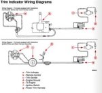
Trim wiring help!

Ashton.r

Seaman Apprentice
Joined
Jul 21, 2015
Messages
44
[FONT=arial, helvetica, sans-serif]hey guys i seriously cannot find anything to help me understand my situation. first off the outboard is an 1983 (what i believe) mercury black max 150 for my trim and tilt Im trying to figure out where two other wires coming from the outboard go. i have two wire connected to the pump, blue and green. the trim and tilt works great goes up and down properly, trailer circuit works. what im lost about is there is two other wires coming from the motor it self and i have no idea where they go, one i can't tell the color, and the other is a brown/tan. is one a ground and the other goes to the trim gauge? i want to wire in a trim gauge. is this done through the harness that plugs into the control box. (Same harness that the tach goes to). or does the trim gauge go to the two wires coming from the outboard?[/FONT]

[FONT=arial, helvetica, sans-serif]Thanks guys![/FONT]
 

DeepBlue2010

Lieutenant
Joined
Aug 19, 2010
Messages
1,305
Most likely those are the wires for your trim sender unit. Here is a quick way to verify if you have an ohm-meter or multi meter.

Put the engine all the way down
Set the ignition switch to "ON" position
Set your tester to reading Ohms (resistance measurement)
Insert you tester leads inside those two wires
Start raising the engine up

If the resistance reading on the tester started to increase as the engine is moving up, this is for sure you trim sending unit wires.

The brown wire is usually brown/white not brown/tan. The receiving end of the trim sender unit is coming out of the cable that is going to the engine harness. They are not part of the harness itself (as in they don't plug into the socket) but they are coming out of the harness just before the end of it. The wire is also Brown/White to avoid any confusion. When you verify that this is the trim sending unit, plug the wires from the engine into the wire that is at the end of the harness.

The other end of this wire ) near your dash board) will come from two different places depends on if you have the key inside the throttle control or if you have a separate ignition switch on the dash. If it is the former, there is a cable coming out of the throttle control and you will find the other end if this wire coming out of this cable. If it is the former, the wire is coming from the harness cable near the dash. Either case, it is also Brown/White.

Hope this helps, best of luck to you.


TrimSendingUnit outboard150.GIF
 
Last edited:

Ashton.r

Seaman Apprentice
Joined
Jul 21, 2015
Messages
44
Dude you are the man!!! thanks for the reply man well informed! mvp! illl give it a test and see what i come up with!
 

DeepBlue2010

Lieutenant
Joined
Aug 19, 2010
Messages
1,305
Before you attempt to measure the resistance between the two wires, make sure there is no voltage difference between them. Set your meter to measure DC Volt and read the potential difference between the two terminals. It should be Zero. If so, then continue as described above.
 

Ashton.r

Seaman Apprentice
Joined
Jul 21, 2015
Messages
44
ok heres an update:

i tested the two wires coming from the back and got zero on voltage test and no resistance results trimming up or down. I trimmed the motor way up to look under to see where these wires are running to. They go to the contact points on motor and the motor bracket on the port side. the contact on the motor is a strip of metal and the contact on the motor bracket is a bolt head. i have the starboard already hooked up to the two plug is off the wiring that goes to the pump. the starboard wires are blue and green. the port side has no color indicator on one of the wires but the second wire on the port side has a little piece of rubber around it that is the color brown, im assuming brown but the wires are dirty so im not 100%.

secondly i traced all the wiring for the trim system. i do have the key wired in the control box not the dash. so the only brown and white wire i traced is one that comes off the gauge harness. I didnt have time to toss the gauge on the brown and white wire to test it but i'm assuming this should be my sender signal wire, as you and mercury color codes say. there isnt any other plug in near or around the box, nor is there any around the pump.
 

DeepBlue2010

Lieutenant
Joined
Aug 19, 2010
Messages
1,305
Post some pictures from the engine side that clearly shows the two wires in question. Using the process of elimination, test resistance between ground and the Brown/White wire that is coming out of the throttle control box either by multi-meter set to measure resistance or by connecting a trim gauge. If there is a signal on this wire, the two wires in question have nothing to do with trim sender unit since the trim sending signal is fully functional without them.

If you don't get signal on that wire, we still don't know if they are the trim sender wires or not since the sender could be bad and that is why it is not controlling the signal.

I am not sure if you are doing this with the engine cover on or off but try to remove the engine cover and look for the trim sending unit and see where the wires coming from it go. It should be very clear from inside

Again picture would help great deal. Try to get an over all picture and then a close up ones.
 
Last edited:
Top