Selectrim-Abandon or hook back up?

docben

Seaman
Joined
Jan 13, 2024
Messages
50
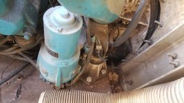
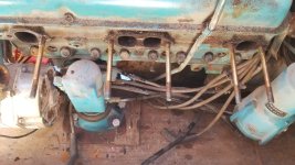
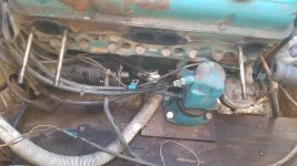
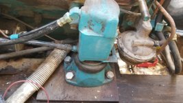
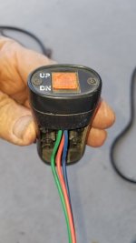
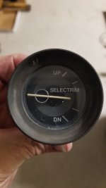
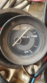
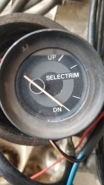
I have a Selectrim installed on my 1985 Beachcraft Cuddy with 5.7L (305ci) and right now it does not work as the previous owners cut the electrical wires and just left the hydraulic parts installed.

This trim system was designed decades ago and I wonder just how many boat owners out there that have this trim system have it still hooked up and operational? Does this trim system make that much difference in the water? Has it worked out that well over the years, that owners kept the system operational?

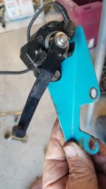
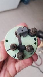
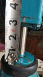
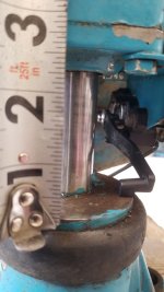
I think all I have to do is hook the wiring back up and get it operational. The parts look OK. The hydraulic lines are good.

So is it worth the time to get it back fully operational?

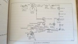
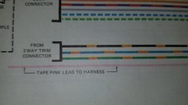
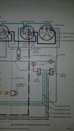
The OMC Stern Drive service manual (part no 506580 K-79) has very little on this. Maybe a newer manual has more info, especially the wiring diagram?

Any help from those who have this system is appreciated.
 

Attachments

  • 20231224_120241.jpg
    20231224_120241.jpg
    1.1 MB · Views: 6
  • 20240114_110446.jpg
    20240114_110446.jpg
    1.5 MB · Views: 6
  • 20240114_110548.jpg
    20240114_110548.jpg
    2.8 MB · Views: 6
  • 20240114_110604.jpg
    20240114_110604.jpg
    2.5 MB · Views: 6

Scott Danforth

Grumpy Vintage Moderator still playing with boats
Staff member
Joined
Jul 23, 2011
Messages
47,591
With a stringer, it's almost required. It is the method of trimming an OMC stringer

I would recommend you fix it
 

southkogs

Moderator
Staff member
Joined
Jul 7, 2010
Messages
14,798
Not hard to fix it, and it does help. I ran for quite a while without it (and they made models without trim), but it is helpful.
 

Bondo

Moderator
Staff member
Joined
Apr 17, 2002
Messages
70,536
Ayuh,.... Fix it, 'n the hull will plane out, much more efficiently,....
No more plowing through the water,.....
 

kenny nunez

Captain
Joined
Jun 20, 2017
Messages
3,076
Try to run the pump by jumping from the battery, if it runs all the better. If it does not most probably the brushes are stuck in their holder. While holding the field frame down gently remove the cover, there may be a small ball bearing on the end of the armature. Stick the ball bearing with some heavy grease to the armature. Cut a 6” length of coat hanger wire snd bend it evenly into a “V” shaped tool. Free up the brushes then use the tool to hold the brushes back, put the cover back on and pull the tool out. Power steering fluid is a good fluid for the system. The seals in the rams are replaceable and can be matched up at any hydraulic store.
Sierra marine has a complete pump and motor. # 18-6257
 

docben

Seaman
Joined
Jan 13, 2024
Messages
50
Ayuh,.... Fix it, 'n the hull will plane out, much more efficiently,....
No more plowing through the water,.....
Everyone so far says "fix it", so I will. I would like to find more info in a manual. It has been stated that Seloc was not good and get the factory OEM one, but so far comparing my Seloc to the OMC, Seloc has much more info. Maybe no manual needed for someone that has worked on these before.

Seloc has several wire identifications in the appendix so will track down the relevant wires and hook them back up. Cross my fingers.
 

matt167

Captain
Joined
Sep 27, 2012
Messages
3,713
Seloc may have more info. But it probably isn’t the right info. They are good as a general guide… Sometimes
 

docben

Seaman
Joined
Jan 13, 2024
Messages
50
Seloc may have more info. But it probably isn’t the right info. They are good as a general guide… Sometimes
Having something, rather that nothing is a start.
The OMC manual doesn't even show the trim pump and associated trim motor mounts.

So I will see if the pump motor runs, with plenty of fluid in the reservoir. Seloc says 14 fl oz is total capacity.

A section in Seloc states..."Energize the pump to extend the rods. The engine should travel up through the trim range (4 degrees stern drive out to 3 degrees in) in 9-13 seconds and require 25-30 amps at 12 volts (13.5 volts initial). In the down direction current draw should be approximately 25-30 amps for 8.5 seconds at 12 volts. Stall current should be about 60 amps minimum in the full down position."

Is the above wrong information?? If so what is the correct info?
 

Scott Danforth

Grumpy Vintage Moderator still playing with boats
Staff member
Joined
Jul 23, 2011
Messages
47,591
I believe select trim has its own manual
 

docben

Seaman
Joined
Jan 13, 2024
Messages
50
Looked for it on ebay and internet and don't find it. I've ordered a newer manual that is more specific for my model number. Hope this helps with the unknowns.
UPDATE.
Never found a separate manual for the SelecTrim, but the new (old) manual I just got, Part # 983441 covers my model engine, and has more info on this trim setup. Chapter 10 (21 pages) covers a lot but still doesn't tell me, for example, the max distance the piston/rod can travel upon toggling the switch. There is a sending unit attached to the front right engine mount that has a lever that moves up and down to limit max height. I tested the sender per the manual and it performs as it should from zero to 100 Ohms.

As you see from the photo, the max travel is about 1.5 inches.

Is that all the travel to expect? The manual gives no clue.

I also noticed a leak in one of the cylinders, so will replace all the seals while the engine is out. I can't imagine doing this while engine is in the boat. The fluid I am using is STP power steering, not what the manual calls for...OMC Power Trim and Tilt fluid, which may not be made anymore.

I am wanting to run the whole system while engine is out, using Amperage and Voltage gauges inline with wiring diagram to see if there are sufficient loads on the motor. The manual describes an Electrical Check, measuring voltage drops, and current draw to be sure the motor is good.

Any other things I should do?? Thanks.
 

Attachments

  • 20240207_144217.jpg
    20240207_144217.jpg
    947.4 KB · Views: 2
  • 20240207_145300.jpg
    20240207_145300.jpg
    2 MB · Views: 2
  • 20240207_145508.jpg
    20240207_145508.jpg
    2.5 MB · Views: 2
  • 20240206_143405.jpg
    20240206_143405.jpg
    1.5 MB · Views: 1

froggy1150

Master Chief Petty Officer
Joined
Nov 3, 2017
Messages
803
So I have the ford. So not apples to apples.
1. My sender has zero to do with what the trim does. It just reports to a Guage on the dash where the motor is sitting....just like a gas Guage.
2. I think my cylinders have more travel than that
 

kenny nunez

Captain
Joined
Jun 20, 2017
Messages
3,076
Just be sure that the rams are sealed and not leaking. Sometimes the cover that retains the piston will be cracked. Do not worry about travel of the rams. When the engine is back in the boat be sure that the engine does not “lean over” to one side when the rams are at the end of travel. You may have to shim one side the keep the engine level through the full range of travel.
The 50 amp glass fuses can cause some problems. I suggest replacing them with a circuit breaker of at least 50 or more amps.
 

docben

Seaman
Joined
Jan 13, 2024
Messages
50
Just be sure that the rams are sealed and not leaking. Sometimes the cover that retains the piston will be cracked. Do not worry about travel of the rams. When the engine is back in the boat be sure that the engine does not “lean over” to one side when the rams are at the end of travel. You may have to shim one side the keep the engine level through the full range of travel.
The 50 amp glass fuses can cause some problems. I suggest replacing them with a circuit breaker of at least 50 or more amps.
I will be replacing all seals first, so thanks for the suggestion.

When I look more closely at the wiring diagram, I am pretty sure the only function of the sender is to report the travel to the dial indication on the dash. After the seals are replaced, I shall test the working order of the sender.

As for the 2 glass fuses, they look ok to me. What problems are possible?
 

kenny nunez

Captain
Joined
Jun 20, 2017
Messages
3,076
The holders get weak and I have had a few times where the fuse would check for continuity but not passing any current and yet not showing any signs of being burned. Another problem is where they are in relation to the engine cover’s closing, the holders are supposed to be water proof but somehow they will get corroded. The GM engine’s distributor will also get water in them through the small screen in the side of the Mallory style distributor.
 

docben

Seaman
Joined
Jan 13, 2024
Messages
50
Trying also to hook up all three mechanical devices (3-wire switch, sender unit, and gauge) and test before the engine gets put back in. Looking at the wiring diagram it would seem rather straightforward, but not working so those who are better than me at wiring, please suggest how to wire. I post photos of the hardware and wiring diagram.
 

Attachments

  • 20240209_155114.jpg
    20240209_155114.jpg
    827.1 KB · Views: 3
  • 20240209_160330.jpg
    20240209_160330.jpg
    2.3 MB · Views: 3
  • 20240209_160352.jpg
    20240209_160352.jpg
    1.2 MB · Views: 4
  • 20240209_170749.jpg
    20240209_170749.jpg
    899.1 KB · Views: 4
  • 20240209_172125.jpg
    20240209_172125.jpg
    775 KB · Views: 3

kenny nunez

Captain
Joined
Jun 20, 2017
Messages
3,076
The solenoids always gave a lot of trouble. If they have 4 terminals then they are non grounded base types. They look just like automotive styles but will not work since the “I“ terminal is hot when the solenoid is triggered and since it is connected to a ground wire which burns out the solenoid. Quite often was the kind of problem that showed up at my shop because someone substituted an automotive style.
If the solenoids have 3 terminals then they are grounded base style but still cause problems from internal corrosion.
Wire colors are easy to remember, blue sky and green grass for up and down.
 

docben

Seaman
Joined
Jan 13, 2024
Messages
50
The solenoids always gave a lot of trouble. If they have 4 terminals then they are non grounded base types. They look just like automotive styles but will not work since the “I“ terminal is hot when the solenoid is triggered and since it is connected to a ground wire which burns out the solenoid. Quite often was the kind of problem that showed up at my shop because someone substituted an automotive style.
If the solenoids have 3 terminals then they are grounded base style but still cause problems from internal corrosion.
Wire colors are easy to remember, blue sky and green grass for up and down.
For my setup, its not the solenoids that are the issue. They work fine so far.

Finally got all 3 items working together! Yea!

After cycling the hydraulic trim motor up and down for several cycles, the max extension of the cylinder rods is 2-1/2 on the left and 2-3/8 on the right, with the corresponding gauge reading full UP and full DN.

DN means BOW DOWN...UP means BOW UP. Full cylinder extension is when BOW full DN.

Hope all this helps others.
 

Attachments

  • 20240210_102418.jpg
    20240210_102418.jpg
    1.1 MB · Views: 0
  • 20240210_103017.jpg
    20240210_103017.jpg
    1.2 MB · Views: 0
  • 20240210_103041.jpg
    20240210_103041.jpg
    1.1 MB · Views: 0
  • 20240210_103115.jpg
    20240210_103115.jpg
    971.5 KB · Views: 0
Top