remote motor control on-off-start

ttles714

Cadet
Joined
Jun 13, 2009
Messages
16
I am looking to start, run and stop my 2007 F250 from behind the engine when it is on the trailer, I want to avoid having to go to the helm when i am servicing . Is there a "tool" for this ??? I can't seem to find a wiring schematic if I have to make one .... Any help or information welcome ....thanks
 

boscoe99

Commander
Joined
Aug 22, 2013
Messages
2,358
Wiring diagram is in the back of the applicable service manual.

No tool available. You will have to devise a means on your own.

Most practical and cost effective way would be to disconnect the ten pin connector at the front of the motor. On the motor side connector jumper the red wire terminal to the yellow wire terminal. That will turn the ignition on.

To crank and start the motor momentarily jumper the red wire terminal to the brown wire terminal. That will engage the starter motor.

To stop the motor jumper the black wire terminal to the white wire terminal.

Or you can buy a used Yamaha 703 control box or an aftermarket 703 control box in which case you will disconnect the ten pin coupler on the motor and connect the ten pin connector from the 703 control box.
 

ttles714

Cadet
Joined
Jun 13, 2009
Messages
16
good information , pretty much what I was looking for .. I think what i am going to do is find a 10 pin harness to plug into the motor's ten pin connector ... Then modify that harness with a couple of switches .. If you have the time, could you take a look at the link below and let me know if this would work out for a starting point for this project .....thanks very much much
 

Chris1956

Supreme Mariner
Joined
Mar 25, 2004
Messages
29,114
They have remote starter cables for Mercs and other motors. Mechanics use them on motors mounted on stands. You might look for them.

The other choice is to make one. Find a short engine cable extension and a keyswitch and wire it up.
 

boscoe99

Commander
Joined
Aug 22, 2013
Messages
2,358
They have remote starter cables for Mercs and other motors. Mechanics use them on motors mounted on stands. You might look for them.

The other choice is to make one. Find a short engine cable extension and a keyswitch and wire it up.
What Yamaha calls a boat in a box. Box being used to segregate the motor from the boat when trouble shooting.
 

ttles714

Cadet
Joined
Jun 13, 2009
Messages
16
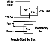
Boscoe 99 ... thanks buddy ... Based on what you told me ... here is what i am going to put together .. I am going to mount the switches in a small project box.. I have a momentary switch with a cover that has to be lifted to activate. This adds a little more safety to avoid accidental activation.... Thanks for the link to the extension cable and for letting me "pick your brain" Much Appreciated !! tony
1787662881971.png
 

ttles714

Cadet
Joined
Jun 13, 2009
Messages
16
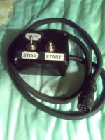
Ok >>> so I finally got around to putting this together ... Pretty simple and straight forward .. NOT !!! I picked up an old used harness FROM a 703 control box .. I kept about 6 feet OR WIRE from the female connector and hooked up all the wiring and switches .... Tried it out and nothing !!! Long story Short >>> In the harness female connector, the 12V+ and 12v- were in reverse positions.. Opposite that of my motor and any diagram I had ... I wound up using the black as positive and the red as negative . I don't really understand why this occurred ????? All other wires were in the proper position...Did Yamaha change harness part #'s ??? ANY ONE HAVE AN ANSWER ???
 

ttles714

Cadet
Joined
Jun 13, 2009
Messages
16
picture of harness and control .. still can't figure out why this harness had the 12v neg and pos in opposite positions from the engine and any schematic I looked at ... The connector is intact and was not modified ..... So To be clear ,,, the positive pin on the motor lines up with the negative pin on the control harness and the negative pin on the motor lines up with the positive motor pin !!
 

Attachments

  • remote service start.JPG
    remote service start.JPG
    1.8 MB · Views: 2

ttles714

Cadet
Joined
Jun 13, 2009
Messages
16
So What I have on this harness is just what you posted ...EXCEPT !!! the black and red terminals and wires are opposite the drawing on the harness .... The motor has the red wire at 12 o'clock and the Black wire at 6 o'clock... The harness has those two wires in opposite positions... I had to connect The harness Black connects to the motor red !! And the harness red to the motor black. All the other wires are in proper position ... The harness was an old used harness that was lying around the shop .. I figured it out When I had the connection of red to red and black to black and my meter was showing reverse polarity . Once I connected harness black to motor red it all worked ... CRAZY !!!! ..
 

ttles714

Cadet
Joined
Jun 13, 2009
Messages
16
Basically the hot lead and the ground wire in the harness are the right colors but in opposite positions ,,,,, so the black ground is actually 12v + and the red at 12 o'clock is actually 12v - .. The Red from the motor lines up with the black harness wire and the black from the motor lines up with the red from the harness.
 
Last edited:

boscoe99

Commander
Joined
Aug 22, 2013
Messages
2,358
So What I have on this harness is just what you posted ...EXCEPT !!! the black and red terminals and wires are opposite the drawing on the harness .... The motor has the red wire at 12 o'clock and the Black wire at 6 o'clock... The harness has those two wires in opposite positions... I had to connect The harness Black connects to the motor red !! And the harness red to the motor black. All the other wires are in proper position ... The harness was an old used harness that was lying around the shop .. I figured it out When I had the connection of red to red and black to black and my meter was showing reverse polarity . Once I connected harness black to motor red it all worked ... CRAZY !!!! ..
I am guessing that someone rewired your used 703 ten pin harness.

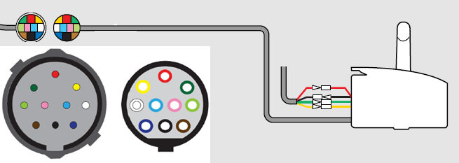
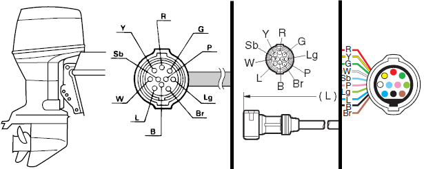
Below are three different illustrations showing how the side of the ten pin harness towards the motor is configured.

 
Top